
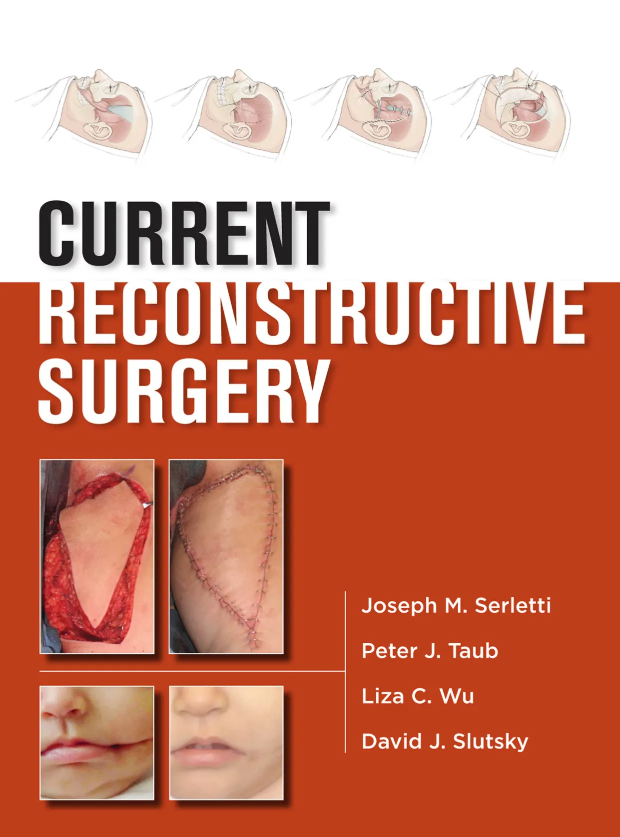
CURRENT RECONSTRUCTIVE SURGERY Joseph M. Serletti Peter J. Taub Liza C. Wu David J. Slutsky
Current
Reconstructive
Surgery
Notice
Medicine is an ever-changing science. As new research and clinical experience broaden our knowl-
edge, changes in treatment and drug therapy are required. The authors and the publisher of this
work have checked with sources believed to be reliable in their efforts to provide information that is
complete and generally in accord with the standards accepted at the time of publication. However,
in view of the possibility of human error or changes in medical sciences, neither the authors nor
the publisher nor any other party who has been involved in the preparation or publication of this
work warrants that the information contained herein is in every respect accurate or complete, and
they disclaim all responsibility for any errors or omissions or for the results obtained from use of the
information contained in this work. Readers are encouraged to confirm the information contained
herein with other sources. For example and in particular, readers are advised to check the product
information sheet included in the package of each drug they plan to administer to be certain that the
information contained in this work is accurate and that changes have not been made in the recom-
mended dose or in the contraindications for administration. This recommendation is of particular
importance in connection with new or infrequently used drugs.
Current
Reconstructive
Surgery
Editors
Joseph M. Serletti, MD, FACS
Henry Royster—William Maul Measey
Professor of Surgery and Chief
Division of Plastic Surgery
Vice Chair (Finance), Department of Surgery
University of Pennsylvania
Philadelphia, Pennsylvania
Peter J. Taub, MD, FACS, FAAP
Professor, Surgery and Pediatrics
Chief, Craniomaxillofacial Surgery
Co-Director, Mount Sinai Cleft and
Craniofacial Center
Division of Plastic and Reconstructive Surgery
Mount Sinai Medical Center and
Kravis Children’s Hospital
New York, New York
Liza C. Wu, MD, FACS
Assistant Professor
Director of the Microsurgery Program and
Clinical Research Program
Division of Plastic Surgery
University of Pennsylvania Health Systems
Philadelphia, Pennsylvania
David J. Slutsky, MD
Clinical Assistant Professor
Department of Orthopedics
Chief of Reconstructive Surgery
Harbor-UCLA Medical Center
Los Angeles, California
Private Practice
The Hand and Wrist Institute
Torrance, California
New York Chicago San Francisco Lisbon London Madrid Mexico City
Milan New Delhi San Juan Seoul Singapore Sydney Toronto
Copyright © 2013 by The McGraw-Hill Companies, Inc. All rights reserved. Except as permitted under the United States Copyright Act of 1976, no part of this
publication may be reproduced or distributed in any form or by any means, or stored in a database or retrieval system, without the prior written permission of the
publisher.
ISBN: 978-0-07-181403-4
MHID: 0-07-181403-5
The material in this eBook also appears in the print version of this title: ISBN: 978-0-07-147723-9,
MHID: 0-07-147723-3.
All trademarks are trademarks of their respective owners. Rather than put a trademark symbol after every occurrence of a trademarked name, we use names in an
editorial fashion only, and to the benefi t of the trademark owner, with no intention of infringement of the trademark. Where such designations appear in this book,
they have been printed with initial caps.
McGraw-Hill eBooks are available at special quantity discounts to use as premiums and sales promotions, or for use in corporate training programs. To contact a
representative please e-mail us at bulksales@mcgraw-hill.com.
TERMS OF USE
This is a copyrighted work and The McGraw-Hill Companies, Inc. (“McGraw-Hill”) and its licensors reserve all rights in and to the work. Use of this work is subject
to these terms. Except as permitted under the Copyright Act of 1976 and the right to store and retrieve one copy of the work, you may not decompile, disassemble,
reverse engineer, reproduce, modify, create derivative works based upon, transmit, distribute, disseminate, sell, publish or sublicense the work or any part of it
without McGraw-Hill’s prior consent. You may use the work for your own noncommercial and personal use; any other use of the work is strictly prohibited. Your
right to use the work may be terminated if you fail to comply with these terms.
THE WORK IS PROVIDED “AS IS.” McGRAW-HILL AND ITS LICENSORS MAKE NO GUARANTEES OR WARRANTIES AS TO THE ACCURACY,
ADEQUACY OR COMPLETENESS OF OR RESULTS TO BE OBTAINED FROM USING THE WORK, INCLUDING ANY INFORMATION THAT CAN
BE ACCESSED THROUGH THE WORK VIA HYPERLINK OR OTHERWISE, AND EXPRESSLY DISCLAIM ANY WARRANTY, EXPRESS OR IMPLIED,
INCLUDING BUT NOT LIMITED TO IMPLIED WARRANTIES OF MERCHANTABILITY OR FITNESS FOR A PARTICULAR PURPOSE. McGraw-Hill and
its licensors do not warrant or guarantee that the functions contained in the work will meet your requirements or that its operation will be uninterrupted or error free.
Neither McGraw-Hill nor its licensors shall be liable to you or anyone else for any inaccuracy, error or omission, regardless of cause, in the work or for any damages
resulting therefrom. McGraw-Hill has no responsibility for the content of any information accessed through the work. Under no circumstances shall McGraw-Hill
and/or its licensors be liable for any indirect, incidental, special, punitive, consequential or similar damages that result from the use of or inability to use the work,
even if any of them has been advised of the possibility of such damages. This limitation of liability shall apply to any claim or cause whatsoever whether such claim
or cause arises in contract, tort or otherwise.
I dedicate this to my wife Bonnie and my daughters
Lacey and Tate for their immeasurable support.
—Joseph M. Serletti, MD, FACS
To Dylan, Justin, and Joey for their support and understanding
especially when work occasionally takes me away from my family.
—Peter J. Taub, MD, FACS, FAAP
To my best friends Brett and Jesse for all of the joy
and love that you bring to my life.
—David J. Slutsky, MD
To my mentors who have taught me and to my family who
support me in the practice of plastic surgery.
—Liza C. Wu, MD, FACS
This page intentionally left blank
vii
Contents
Contributors ix
1 Principles of Wound Healing and
Fundamentals of Wound Repair 1
Kristina D. O’Shaughnessy and Thomas A. Mustoe
2 Perforator Flaps 11
Christoph Heitmann and Robert J. Allen
3 Alloplastic Craniofacial Implants 25
Michael J. Yaremchuk
4 Reconstructive Transplantation: Evolution,
Experience, Emerging Insights 37
Vijay S. Gorantla, W.P. Andrew Lee,
and Joseph E. Losee
5 Negative Pressure Wound Therapy 51
Mark B. Schoemann and Christopher Lentz
6 Anesthesia for Plastic Surgery 61
Meredith S. Collins, Sameer Bashey,
and Laurence M. Hausman
7 Malignant Skin Lesions 69
Wesley N. Sivak, Roee E. Rubinstein,
and Howard D. Edington
8 Vascular Malformations 79
David W. Low and M. Renee Jespersen
9 Hemangiomas 91
David W. Low and Richard L. Agag
10 Burn Reconstruction 101
Brian M. Parrett and Julian J. Pribaz
11 Head and Neck Embryology 113
Geoffrey H. Sperber
12 Cleft Lip Repair 125
William Y. Hoffman
13 Cleft Palate 133
Peter J. Taub and Joseph E. Losee
14 Secondary Deformities of the Cleft Lip,
Palate, and Nose 141
Jamal M. Bullocks and Samuel Stal
15 Velopharyngeal Insuffi ciency 159
Rachel A. Ruotolo and Richard E. Kirschner
16 Craniosynostosis 167
Mitchel Seruya, Stephen B. Baker,
and Jeffrey Weinzweig
17 Hemifacial Microsomia 177
Fernando Molina
18 Craniofacial Clefts 189
Jeffrey A. Fearon
19 Orthognathic Surgery and Cephalometric Analysis 197
Jesse A. Goldstein and Stephen B. Baker
20 Skull Base Surgery 209
Stephen P. Beals and Hahns Y. Kim
21 Overview of Facial Fractures 219
Alexandre Marchac, Jeffrey D. Larson,
and Stephen M. Warren
22 Orbital Fractures and Deformities 233
Joshua Fosnot and Joseph M. Serletti
23 Frontal Sinus Fractures 245
Matthew G. Stanwix and Eduardo D. Rodriguez
24 Nasal Fractures 255
Ronald E. Hoxworth and Rod J. Rohrich
25 Midface and Maxillary Fractures 265
Adam J. Oppenheimer and Steven R. Buchman
26 Mandibular Fractures 279
Jack C. Yu and Ian F. Wilson
27 Panfacial Fractures 291
Daniel Y. Maman and Mark L. Smith
28 Pediatric Facial Fractures 305
Sanjay Naran, Ahmed M. Afi fi , and Joseph E. Losee
29 Reconstruction of the Ear 315
Christopher J. M. Brooks
30 Reconstruction of the Nose 325
Peter J. Taub
viii • CONTENTS
31 Lip Reconstruction 335
Naveen K. Ahuja, Robert J. Morin, and
Mark S. Granick
32 Cheek Reconstruction 343
Richard A. Hopper, Scott D. Imahara,
Jon P. Ver Halen, and Joseph S. Gruss
33 Eyelid Reconstruction and Ptosis Repair 355
Lisa R. David and Claire Sanger
34 Scalp, Calvarial, and Forehead
Reconstruction 369
Matthew R. Swelstad and Michael L. Bentz
35 Head and Neck Cancer 379
Stephan Ariyan
36 Oral Cancer 419
Suhail K. Mithani and Anthony P. Tufaro
37 Intraoral Reconstruction 431
Frederic W.-B. Deleyiannis
38 Mandibular Reconstruction 445
Joseph J. Disa
39 Reconstruction of the Paralyzed Face 457
Christopher A. Derderian and Oksana Jackson
40 Alopecia 471
Edward H. Davidson, Keith Jeffords,
and Ernest K. Manders
41 Breast Cancer 481
Gretchen Ahrendt
42 Alloplastic Breast Reconstruction 493
Louis P. Bucky and Alexander J. Gougoutas
43 Autologous Breast Reconstruction 501
Joshua Fosnot and Joseph M. Serletti
44 Reduction Mammaplasty 517
Michael N. Mirzabeigi and Liza C. Wu
45 Advances in Mastopexy 525
Scott L. Spear, Mark Warren Clemens,
and Adam D. Schaffner
46 Breast Augmentation 541
Vu T. Nguyen
47 Congenital Breast Deformities 555
S. Alex Rottgers, Derek Fletcher,
Angela Song Landfair, and Kenneth C. Shestak
48 Acellular Dermal Matrix in Aesthetic Revisionary
Breast Surgery 567
G. Patrick Maxwell and Allen Gabriel
49 Physical and Radiologic Evaluation of the Hand 579
Bradley A. Hubbard and Matthew J. Concannon
50 Soft Tissue Reconstruction of the
Upper Extremities 591
Elvin G. Zook and Srdjan A. Ostric
51 Fractures of the Hand and Wrist 603
Jeffrey M. Jacobson, Walter B. McClelland, Jr.,
and James P. Higgins
52 Management of Hand Infections 613
Suhail Kanchwala and Benjamin Chang
53 Compressive Neuropathies in the Upper Extremity 621
David J. Slutsky
54 Replantation and Revascularization 635
Bradon J. Wilhelmi and Scott M. Schulze
55 Tendon Transfers 651
Paul A. Martineau and Thomas Trumble
56 Congenital Hand Anomalies 663
Brian A. Pinsky and Jaimie T. Shores
57 Brachial Plexus 673
Julia K. Terzis and Zinon T. Kokkalis
58 Dupuytren’s Disease 691
Andrew J. Watt and James Chang
59 Rehabilitation of the Injured Hand 701
Michele A. Leadbetter and James P. Higgins
60 Reconstruction of the Chest – Congenital
and Acquired Anomalies and Defects 713
Norman H. Schulman and Tara Lynn Huston
61 Abdominal Wall Reconstruction 719
Devinder P. Singh, Helen G. Hui-Chou,
and Ronald P. Silverman
62 Reconstruction of the Perineum and Genitalia 727
Aaron T. Pelletier and Lawrence J. Gottlieb
63 Lower Extremity Reconstruction 749
Amir H. Tahernia and Lawrence S. Levin
64 Pressure Sores 763
Lisa C. Moody, Wesley T. Myers, John D. Bauer,
and Linda G. Phillips
65 Lymphedema 771
Richard W. Dabb
66 Foot and Ankle Reconstruction 779
Mark Warren Clemens and Christopher E. Attinger
67 Postbariatric Surgery Reconstruction 793
Jonathan W. Toy and J. Peter Rubin
Index 805
ix
Contributors
Ahmed M. Afi fi , MD
Assistant Professor
Division of Plastic Surgery
University of Wisconsin
Madison, Wisconsin
Associate Professor
Department of Plastic Surgery
Cairo University
Cairo, Egypt
Richard L. Agag, MA, MD
Division of Plastic Surgery
University of Pennsylvania School of Medicine
Philadelphia, Pennsylvania
Gretchen Ahrendt, MD, FACS
Associate Professor of Surgery
Division of Surgical Oncology
Co-Director Comprehensive Breast Cancer
Program of University of Pittsburgh Medical Center
Magee-Womens Hospital of University of Pittsburgh
Medical Center
Pittsburgh, Pennsylvania
Naveen K. Ahuja, MD
Fellow, Microvascular Reconstructive Surgery
Division of Plastic Surgery
University of Pittsburgh Medical Center
Pittsburgh, Pennsylvania
Robert J. Allen, MD
Clinical Professor
Department of Plastic Surgery
New York University
New York, New York
Stephan Ariyan, MD, MBA
Clinical Professor of Surgery
(Plastic Surgery, Otolaryngology)
Yale University School of Medicine
New Haven, Connecticut
Associate Chief
Department of Surgery
Yale-New Haven Hospital
New Haven, Connecticut
Christopher E. Attinger, MD
Professor
Department of Plastic Surgery
Georgetown University School of Medicine
Washington, District of Columbia
Chief
Division of Wound Healing
Georgetown University School of Medicine
Washington, District of Columbia
Stephen B. Baker, MD, DDS, FACS
Professor and Program Director
Department of Plastic Surgery
Georgetown University Hospital
Washington, District of Columbia
Co-Director
Craniofacial Anomalies Program
Inova Fairfax Hospital
Falls Church, Virginia
Sameer Bashey, MD
Division of Plastic and Reconstructive Surgery
Mount Sinai School of Medicine
New York, New York
John D. Bauer, MD
Associate Professor
Department of Surgery
University of Texas Medical Branch at Galvetson
Galveston, Texas
Stephen P. Beals, MD, FACS, FAAP
Associate Professor of Plastic Surgery
Mayo Clinic
Medical Director
Barrow Cleft and Craniofacial Center
St. Joseph’s Hospital and Medical Center
Phoenix, Arizona
x • CONTRIBUTORS
Benjamin Chang, MD, FACS
Associate Professor of Clinical Surgery
Division of Plastic Surgery
University of Pennsylvania School of Medicine
Philadelphia, Pennsylvania
Senior Surgeon
Division of Plastic Surgery
The Children’s Hospital of Philadelphia
Philadelphia, Pennsylvania
Mark Warren Clemens, MD
Assistant Professor
Department of Plastic Surgery
MD Anderson Cancer Center
University of Texas
Houston, Texas
Meredith S. Collins, MD
Resident
Division of Plastic Surgery
Mount Sinai School of Medicine
New York, New York
Matthew J. Concannon, MD
Owner
Concannon Plastic Surgery
Columbia, Missouri
Richard W. Dabb, MD
Associate Professor
Department of Surgery
Johns Hopkins University
Baltimore, Maryland
Clinical Professor
Department of Surgery
Milton S. Hershey/Penn State Medical Center
Hershey, Pennsylvania
Lisa R. David, MD, FACS
Professor
Department of Plastic Surgery
Program Director
Department of Plastic Surgery
Wake Forest University
Winston-Salem, North Carolina
Edward H. Davidson, MA (Cantab), MBBS
Resident
Division of Plastic Surgery
University of Pittsburgh Medical Center
Pittsburgh, Pennsylvania
Michael L. Bentz, MD, FACS, FAAP
Professor and Chairman
Division of Plastic Surgery
University of Wisconsin School of Medicine
and Public Health
Madison, Wisconsin
Vice Chairman for Clinical Affairs
Department of Surgery
University of Wisconsin
Madison, Wisconsin
Christopher J. M. Brooks, MD
Attending Physician
Department of Plastic Surgery
Joe DiMaggio Children’s Hospital
Hollywood, Florida
Adjunct Professor
Division of Plastic Surgery
Cleveland Clinic Florida
Weston, Florida
Steven R. Buchman, MD, FACS
M. Haskell Newman Professor in Plastic Surgery
Professor of Neurosurgery
University of Michigan
Medical School
Chief
Pediatric Plastic Surgery
CS Mott Childrens Hospital
Director
Craniofacial Anomalies Program
University of Michigan
Medical Center
Ann Arbor, Michigan
Louis P. Bucky, MD, FACS
Clinical Professor
Plastic and Reconstructive Surgery
The Hospital of the University of Pennsylvania
Philadelphia Pennsylvania
Chief
Plastic and Reconstructive Surgery
Pennsylvania Hospital
Philadelphia, Pennsylvania
Jamal M. Bullocks, MD, FACS
Assistant Professor
Division of Plastic Surgery
Baylor College of Medicine
Houston, Texas
James Chang, MD
Professor and Chief
Division of Plastic Surgery
Stanford University Medical Center
Palo Alto, California
CONTRIBUTORS • xi
Allen Gabriel, MD, FACS
Assistant Professor
Plastic Surgery
Loma Linda University Medical Center
Loma Linda, California
Chief of Plastic Surgery
Department of Plastic Surgery
Southwest Washington Medical Center
Vancouver, Washington
Jesse A. Goldstein, MD
Chief Resident
Department of Plastic Surgery
Georgetown University
Washington, District of Columbia
Vijay S. Gorantla, MD, PhD
Associate Professor of Surgery
Administrative Medical Director,
Reconstructive Transplant Program
Director, Veterans Affairs Pittsburgh
Hand Transplant Program
Department of Plastic and Reconstructive Surgery
Veterans Affairs Hospital
Pittsburgh, Pennsylvania
Lawrence J. Gottlieb, MD, FACS
Professor of Surgery
Director of Burn and Complex Wound Center
Section of Plastic and Reconstructive Surgery/
Department of Surgery
University of Chicago
Chicago, Illinois
Alexander J. Gougoutas, MD
Resident
Division of Plastic Surgery
University of Pennsylvania
Philadelphia, Pennsylvania
Mark S. Granick, MD
Professor and Chief of Plastic Surgery
Division of Plastic Surgery
New Jersey Medical School-UMDNJ
Newark, New Jersey
Joseph S. Gruss, MD, FRCS[C]
Professor
Department of Surgery
Marlys C. Larson Endowed Chair and
Professor in Pediatric Craniofacial Surgery
University of Washington School of Medicine
Seattle, Washington
Attending Surgeon
Division of Plastic and Craniofacial Surgery
Seattle Childrens Hospital and Harborview Medical Center
Seattle, Washington
Frederic W.-B. Deleyiannis, MD, MPhil, MPH, FACS
Associate Professor
Chief, Deptartment of Pediatric Plastic Surgery
Director, Cleft Lip and Palate Clinic
Director, Craniofacial Microsurgery and Trauma
Departments of Surgery and Otolaryngology
The Children’s Hospital and University of Colorado
School of Medicine
Aurora, Colorado
Christopher A. Derderian, MD
Assistant Professor
Department Plastic Surgery
UT Southwestern Medical Center
Children’s Medical Center
Dallas, Texas
Joseph J. Disa, MD, FACS
Attending Surgeon
Plastic and Reconstructive Surgery
Memorial Hospital for Cancer and Allied Diseases
New York, New York
Professor of Surgery
Weill Medical College of Cornell University
New York, New York
Howard D. Edington, MD, MBA
Associate Professor
Department of Surgery
Associate Professor
Department of Dermatology
University of Pittsburgh School of Medicine
Pittsburgh, Pennsylvania
Jeffrey A. Fearon, MD, FACS, FAAP
Director
The Craniofacial Center
Medical City Dallas
Dallas, Texas
Derek Fletcher, MD
Resident
Plastic Surgery
University of Pittsburgh Medical Center
Pittsburgh, Pennsylvania
Joshua Fosnot, MD
Housestaff
Division of Plastic Surgery
University of Pennsylvania School of Medicine
Philadelphia, Pennsylvania
xii • CONTRIBUTORS
Helen G. Hui-Chou, MD
Resident
Department of Plastic and Reconstructive Surgery
Johns Hopkins University and University
of Maryland School of Medicine
Baltimore, Maryland
Tara Lynn Huston, MD
Instructor in Surgery
Department of Surgery, Division of Plastic Surgery
New York Presbyterian Hospital––Weill
Cornell Medical Center
New York, New York
Scott D. Imahara, MD
Plastic and Reconstructive
Hand and Cosmetic Surgery
Palo Alto Medical Foundation—Santa Cruz
Soquel, California
Oksana Jackson, MD
Assistant Professor
Department of Surgery
Perelman School of Medicine at
the University of Pennsylvania
Philadelphia, Pennsylvania
Attending Physician
Division of Plastic Surgery
Children’s Hospital of Philadelphia
Philadelphia, Pennsylvania
Jeffrey M. Jacobson, MD
Resident
Curtis National Hand Center
Union Memorial Hospital
Baltimore, Maryland
Keith Jeffords, MD, DDS
Private Practice
Paramount Plastic Surgery
Smyrna, Georgia
M. Renee Jespersen, MD
Assistant Professor
Department of Plastic Surgery
Children’s Hospital of Philadelphia
Philadelphia, Pennsylvania
Suhail Kanchwala, MD
Assistant Professor of Surgery
Division of Plastic and Reconstructive Surgery
Hospital of the University of Pennsylvania
Philadelphia, Pennsylvania
Laurence M. Hausman, MD
Associate Professor
Department of Anesthesiology
Director
Ambulatory Anesthesiology
Mount Sinai Medical Center
New York, New York
Christoph Heitmann, MD, PhD
Associate Professor
Aesthetic of Plastic Surgery
University of Heidelberg
Heidelberg, Germany
James P. Higgins, MD
Chief
Curtis National Hand Center
MedStar Union Memorial Hospital
Baltimore, Maryland
William Y. Hoffman, MD
Professor and Chief
Division of Plastic and Reconstructive Surgery
Stephen J. Mathes Endowed Chair
Vice Chair, Department of Surgery
University of California
San Francisco, California
Richard A. Hopper, MD, MS
Associate Professor
Department of Surgery
University of Washington
Seattle, Washington
Chief
Surgical Director
Division of Plastic Surgery, Craniofacial Center
Seattle Children’s Hospital
Seattle, Washington
Ronald E. Hoxworth, MD
Assistant Professor
Department of Plastic Surgery
University of Texas Southwestern Medical Center
Dallas, Texas
Chief of Plastic Surgery
North Texas VA Medical Center
Dallas, Texas
Bradley A. Hubbard, MD
Resident
Division of Plastic Surgery
University of Missouri, Columbia
Columbia, Missouri
CONTRIBUTORS • xiii
Lawrence S. Levin, MD, FACS
Paul B. Magnuson Professor of Orthopaedic Surgery
Chairman, Department of Orthopaedic Surgery
Professor of Surgery (Plastic Surgery)
University of Pennsylvania School of Medicine
Philadelphia, Pennsylvania
Attending Physician
Orthopaedic Surgery
Hospital of the University of Pennsylvania
Philadelphia, Pennsylvania
Joseph E. Losee, MD, FACS, FAAP
Professor of Surgery and Pediatrics
Chief, Division of Pediatric Plastic Surgery
University of Pittsburgh Medical Center
Pittsburgh, Pennsylvania
David W. Low, MD
Professor of Surgery
Division of Plastic Surgery
Perelman School of Medicine at
the University of Pennsylvania
Philadelphia, Pennsylvania
Attending Surgeon
Division of Plastic Surgery
Children’s Hospital of Philadelphia
Philadelphia, Pennsylvania
Daniel Y. Maman, MD, MBA
Private Practice
Millennium Aesthetic Surgery
Division of Plastic and Reconstructive Surgery
Mount Sinai School of Medicine
New York, New York
Ernest K. Manders, MD
Professor of Surgery
Division of Plastic and Reconstructive Surgery
University of Pittsburgh Medical Center
Pittsburgh, Pennsylvania
Alexandre Marchac, MD
Chef de Clinique–Assistant des Hôpitaux de Paris
Department of Plastic Surgery
Hôpital Européen Georges Pompidou, Assistance Publique
des Hôpitaux de Paris
Paris, France
Paul A. Martineau, MD, FRCSC
Assistant Professor
Head Section of Upper Extremity Surgery
Division of Orthopaedic Surgery
McGill University Health Center
Montreal, Quebec
Hahns Y. Kim, MD
Resident
Division of Plastic Surgery
Mayo Clinic
Phoenix, Arizona
Richard E. Kirschner, MD, FACS, FAAP
Chief, Section of Plastic and Reconstructive Surgery
Director, Cleft Lip and Palate Center
Nationwide Children’s Hospital
Columbus, Ohio
Professor of Clinical Plastic Surgery and Pediatrics
The Ohio State College of Medicine
Columbus, Ohio
Zinon T. Kokkalis, MD
Senior Fellow
Reconstructive Microsurgery
Department of Surgery, Division of Plastic and
Reconstructive Surgery
Eastern Virginia Medical School
Norfolk, Virginia
Angela Song Landfair, MD
Division of Plastic Surgery and
Department of Epidemiology
University of Pittsburgh
Pittsburgh, Pennsylvania
Jeffrey D. Larson, MD
Chief Resident
Division of Plastic Surgery
University of Wisconsin Hospital and Clinics
Madison, Wisconsin
Michele A. Leadbetter, OTL, CHT
Senior Hand Therapist
Hand Therapy Department
Curtis National Hand Center
Baltimore, Maryland
W. P. Andrew Lee, MD
The Milton T. Edgerton, MD
Professor and Chairman
Department of Plastic and Reconstructive Surgery
Johns Hopkins University School of Medicine
Baltimore, Maryland
Christopher Lentz, MD, FACS, FCCM
Professor of Surgery
University of New Mexico
Albuquerque, New Mexico
xiv • CONTRIBUTORS
Wesley T. Myers, MD
Private Practice
The Woodlands, Texas
Sanjay Naran, MD
Resident
Division of Plastic Surgery
University of Pittsburgh
Pittsburgh, Pennsylvania
Vu T. Nguyen, MD
Assistant Professor
Associate Program Director
Division of Plastic Surgery, Department of Surgery
University of Pittsburgh School of Medicine
Pittsburgh, Pennsylvania
Adam J. Oppenheimer, MD
Resident
Section of Plastic Surgery
University of Michigan
Ann Arbor, Michigan
Kristina D. O’Shaughnessy, MD
Department of Surgery
Division of Plastic Surgery
Feinberg School of Medicine
Northwestern University
Chicago, Illinois
Srdjan A. Ostric, MD
Attending Physician
Department of Plastic Surgery
Resurrection Medical Center
Chicago, Illinois
Brian M. Parrett, MD
Attending Physician
Division of Plastic Surgery and Microsurgery
The Buncke Clinic
San Francisco, California
Aaron T. Pelletier, MD
Zaccone Family Fellow in Reconstructive Microsurgery
Section of Plastic and Reconstructive Surgery
Department of Surgery
University of Chicago Medical Center
Chicago, Illinois
Linda G. Phillips, MD
Professor and Chief
Division of Plastic Surgery
University of Texas Medical Branch at Galveston
Galveston, Texas
G. Patrick Maxwell, MD, FACS
Clinical Professor
Department of Plastic Surgery
Loma Linda University
Loma Linda, California
Clinical Assistant Professor
Department of Plastic Surgery
Vanderbilt University
Nashville, Tennessee
Walter B. McClelland, Jr., MD
Fellow–Hand, Microvascular & Upper Extremity Surgery
Curtis National Hand Center
Union Memorial Hospital
Baltimore, Maryland
Michael N. Mirzabeigi, MD
Resident Physician
Division of Plastic Surgery
University of Pennsylvania
Philadelphia, Pennsylvania
Suhail K. Mithani, MD
Chief Resident
Department of Plastic Surgery
Johns Hopkins Medical Institutions
Baltimore, Maryland
Fernando Molina, MD
Professor of Plastic and Reconstructive Surgery
Universidad Nacional Autonoma de Mexico
Mexico City, Mexico
Chief of Plastic and Reconstructive Surgery
Hospital General Dr. Manuel Gea Gonzalez
Mexico City, Mexico
Lisa C. Moody, MD
Resident
Department of Surgery
Division of Plastic Surgery
University of Texas Medical Branch
Galveston, Texas
Robert J. Morin, MD
Craniofacial Fellow
Plastic Surgery
Miami Children’s Hospital
Miami, Florida
Thomas A. Mustoe, MD
Lucille and Orion Stuteville Professor of Plastic Surgery
Division of Plastic Surgery
Feinberg School of Medicine
Northwestern University
Chicago, Illinois
CONTRIBUTORS • xv
Claire Sanger, DO
Assistant Professor, Surgery
University of Kentucky
College of Medicine
Lexington, Kentucky
Adam D. Schaffner, MD, FACS
Director
Plastic Surgery Institute of New York
Clinical Assistant Professor,
Weill Cornell Medical College
New York, New York
Mark B. Schoemann, MD
Craniofacial and Pediatric Plastic Surgery Fellow
Children’s Healthcare of Atlanta
Atlanta, Georgia
Norman H. Schulman, MD, FACS
Clinical Professor of Surgery
Department of Surgery, Division of Plastic Surgery
Weil-Cornell Medical College
New York, New York
Director of Plastic Surgery
Lenox Hill Hospital
New York, New York
Scott M. Schulze, MD
Hand Surgeon
Attending Physician, Department of Surgery
Beebe Medical Center
Lewes, Delaware
Joseph M. Serletti, MD, FACS
Henry Royster—William Maul Measey
Professor of Surgery and Chief
Division of Plastic Surgery
Vice Chair (Finance), Department of Surgery
University of Pennsylvania
Philadelphia, Pennsylvania
Mitchel Seruya, MD
Resident Physician
Department of Plastic Surgery
Georgetown University Hospital
Washington, District of Columbia
Kenneth C. Shestak, MD
Professor
Department of Plastic Surgery
University of Pittsburgh School of Medicine
Pittsburgh, Pennsylvania
Brian A. Pinsky, MD
Associate
Long Island Plastic Surgical Group, P. C.
Garden City, New York
Julian J. Pribaz, MD
Professor
Division of Plastic Surgery
Harvard Medical School
Boston, Massachusetts
Eduardo D. Rodriguez, MD, DDS
Associate Professor and Chief
Plastic, Reconstructive and Maxillofacial Surgery
University of Maryland School of Medicine
R. Adams Cowley Shock Trauma Center
Baltimore, Maryland
Rod J. Rohrich, MD, FACS
Professor and Chairman
Department of Plastic Surgery
Crystal Charity Ball Distinguished Chair in Plastic Surgery
Betty and Warren Woodward Chair in Plastic and
Reconstructive Surgery
Distinguished Teaching Professor
University of Texas Southwestern Medical Center
Dallas, Texas
S. Alex Rottgers, MD
Integrated Plastic Surgery Resident
Division of Plastic and Reconstructive Surgery
University of Pittsburgh School of Medicine
Pittsburgh, Pennsylvania
J. Peter Rubin, MD
Chief of Plastic and Reconstructive Surgery
Director
Life After Weight Loss Body Contouring Program
University of Pittsburgh
Pittsburgh, Pennsylvania
Roee E. Rubinstein, MD
Hand Surgery Fellow
Department of Orthopedic Surgery
David Geffen UCLA School of Medicine
Los Angeles, California
Rachel A. Ruotolo, MD
Diplomate
American Board of Plastic Surgery
Craniofacial & Pediatric Plastic Surgery
Long Island Plastic Surgical Group, P.C.
Garden City, New York
xvi • CONTRIBUTORS
Geoffrey H. Sperber, BDS, MSc, PhD, FICD
Professor Emeritus
School of Dentistry
Faculty of Medicine and Dentistry
University of Alberta
Edmonton, Alberta, Canada
Samuel Stal, MD
Professor and Chief, Plastic Surgery
Baylor College of Medicine
Houston, Texas
Matthew G. Stanwix, MD
Clinical Fellow
Department of Plastic and Reconstructive Surgery
Johns Hopkins University School of Medicine
Baltimore, Maryland
Clinical Fellow
Division of Plastic and Reconstructive Surgery
R. Adams Cowley Shock Trauma Center
University of Maryland School of Medicine
Baltimore, Maryland
Matthew R. Swelstad, MD
Physician
Colorado West Otolaryngologists, P.C.
Grand Junction, Colorado
Amir H. Tahernia, MD
Fellow
Division of Plastic Surgery
Duke University School of Medicine
Durham, North Carolina
Private Practice
Plastic and Reconstructive Surgery
Los Angeles, California
Peter J. Taub, MD, FACS, FAAP
Professor, Surgery and Pediatrics
Chief, Craniomaxillofacial Surgery
Co-Director, Mount Sinai Cleft and Craniofacial Center
Division of Plastic and Reconstructive Surgery
Mount Sinai Medical Center and
Kravis Children’s Hospital
New York, New York
Julia K. Terzis, MD, PhD, FACS, FRCS(C)
Clinical Professor
Department of Plastic Surgery
New York University Medical Center
New York, New York
Medical Director
International Institute of Reconstructive Microsurgery
Long Island City, New York
Jaimie T. Shores, MD
Assistant Professor
Department of Plastic and Reconstructive Surgery
Johns Hopkins University School of Medicine
Baltimore, Maryland
Ronald P. Silverman, MD, FACS
Associate Professor
Department of Surgery
University of Maryland School of Medicine
Baltimore, Maryland
Devinder P. Singh, MD
Assistant Professor
Division of Plastic Surgery
University of Maryland School of Medicine
Baltimore, Maryland
Chief
Section of Plastic Surgery
Veterans Affairs Hospital––Baltimore
Baltimore, Maryland
Wesley N. Sivak, MD, PhD
Resident
Division of Plastic and Reconstructive Surgery
Department of Surgery
University of Pittsburgh School of Medicine
Pittsburgh, Pennsylvania
David J. Slutsky, MD
Clinical Assistant Professor
Department of Orthopedics
Chief of Reconstructive Surgery
Harbor-UCLA Medical Center
Los Angeles, California
Private Practice
The Hand and Wrist Institute
Torrance, California
Mark L. Smith, MD, FACS
Assistant Professor
Department of Surgery
Albert Einstein College of Medicine
Bronx, New York
Director
Plastic and Reconstructive Surgery
Continuum Cancer Centers of New York
Beth Israel Medical Center
New York, New York
Scott L. Spear, MD
Professor and Chairman
Department of Plastic Surgery
Georgetown University Hospital
Washington, District of Columbia
CONTRIBUTORS • xvii
Bradon J. Wilhelmi, MD, FACS
Leonard J. Weiner Professor and Chief
Plastic Surgery Residency Program Director
Plastic Surgery
University of Louisville School of Medicine
Louisville, Kentucky
Attending Physician
Plastic Surgery
University of Louisville Hospital
Jewish Hospital, Norton Hospital,
Kosair’s Children’s Hospital
Louisville, Kentucky
Ian F. Wilson, MD, MPH
St. Petersburg, Florida
Liza C. Wu, MD, FACS
Assistant Professor
Director of the Microsurgery Program and Clinical
Research Program
Division of Plastic Surgery
University of Pennsylvania Health Systems
Philadelphia, Pennsylvania
Michael J. Yaremchuk, MD
Professor
Department of Surgery
Harvard Medical School
Boston, Massachusetts
Chief of Craniofacial Surgery
Department of Surgery, Division of Plastic Surgery
Massachusetts General Hospital
Boston, Massachusetts
Jack C. Yu, DMD, MD, MS Ed, FACS
Milford B. Hatcher Professor and Chief
Section of Plastic Surgery
Medical College of Georgia
Augusta, Georgia
Elvin G. Zook, MD
Professor Emeritus
Division of Plastic Surgery
Southern Illinois University
Springfi eld, Illinois
Jonathan W. Toy, MD, FRCS(C)
Attending Physician
Division of Plastic Surgery
University of Alberta
Edmonton, Alberta, Canada
Thomas Trumble, MD
Professor and Chief
Division of Hand and Microvascular Surgery
Department of Orthopaedics & Sports Medicine
University of Washington School of Medicine
Seattle, Washington
Anthony P. Tufaro, DDS, MD, FACS
Associate Professor
Departments of Plastic and
Reconstructive Surgery and Oncology
Johns Hopkins University
Baltimore, Maryland
Attending Surgeon
Department of Plastic and Reconstructive Surgery
Johns Hopkins Hospital
Baltimore, Maryland
Jon P. Ver Halen, MD
Assistant Professor
Department of Plastic Surgery
University of Tennessee
Memphis, Tennessee
Stephen M. Warren, MD
Associate Professor
Department of Plastic Surgery
New York University Medical Center
New York, New York
Andrew J. Watt, MD
Department of Surgery
Division of Plastic and Reconstructive Surgery
Stanford University Hospital & Clinics
Palo Alto, California
Jeffrey Weinzweig, MD, FACS
Chief of Craniofacial Surgery
Director
Craniofacial Anomalies Program
Division of Plastic Surgery
Advocate Illinois Masonic Medical Center
Chicago, Illinois
Director
The Chicago Center for Plastic & Reconstructive Surgery
Chicago, Illinois
This page intentionally left blank
INTRODUCTION
Achievement of adequate wound repair, resolution of heal-
ing, and prevention of pathologic scarring is dependent not
only on a complete understanding of this process but also
on an understanding of wound biomechanics. This chapter
will fi rst focus on certain features of wound biology and
biomechanics where early intervention may prevent heal-
ing complications and problem scarring. The fundamentals
of wound repair, emphasizing choice of incision, suture,
and technique will be explored to further enhance decision
making at the time of tissue restoration. In some cases, fail-
ure of resolution of the normal proliferative response, which
occurs at the resolution phase of normal wound healing, can
lead to proliferative scarring; however, prevention steps are
possible provided the surgeon is knowledgeable about the
pathogenesis of hypertrophic scars. Due to the challenging
treatment of hypertrophic scars and keloids, both surgical
and nonsurgical treatments will be discussed in addition to
prevention strategies.
PRINCIPLES OF WOUND HEALING
Wound Biomechanics
The plastic surgeon must plan each case relative to the bio-
mechanical properties of skin. The principle constituent of
skin is collagen, which is a structural protein organized in
sheets with distinct spatial structural components. Elastin
fi bers are also present in smaller amounts, giving the skin
both elasticity and viscoelastic properties. In other words,
in response to constant force, the skin will stretch and not
fully return to its unstretched state.
Skin Tensions. Placement of skin incisions and resul-
tant scar formation are dependent on both static and
dynamic skin tensions. Static tension is the inherent force
which stretches the skin over the underlying structures
when the body is motionless. 1 The static tension var-
ies enormously within individuals based on anatomic
location—for instance, it is quite high over the sternum
and minimal in the groin. As a person ages, not only does
skin relax and lose elasticity, but the magnitude of tension
also changes. As mentioned earlier, the collagen fi bers have
a spatial orientation, and this organization is refl ected in
static lines of maximal skin tension called Langer lines. An
incision along one of these lines will result in a tension-
free closure with minimal static forces pulling against the
scar. The outcome is a narrow, fi ne, camoufl aged scar. In
contrast, placing an incision against the directional orien-
tation of static skin tension will result in a wider, more vis-
ible scar. This is the sequela of continuous high-magnitude
forces pulling at the healing wound margins. 2
There has been an increased understanding at the cel-
lular level of the impact of mechanical forces on signal
transduction mediated through fi broblast attachments to
the collagen matrix via integrin receptors. 3 , 4 Fibroblasts
respond to tension with cellular proliferation, and col-
lagen synthesis, while fi broblasts relieved of tension
undergo programmed cell death (apoptosis). 5 If tension
is sustained within a healing wound over several weeks,
the excessive fi brosis may lead to pathologic scarring.
Dynamic skin tensions are caused by a variety of changing
forces such as voluntary muscle activity and movement
across joints. These tensions may cause contractures in
areas of high skin mobility if incisions are placed per-
pendicular to Langer lines. 2 The skin in these areas must
c h a p t e r 1
Principles of Wound Healing and
Fundamentals of Wound Repair
Kristina D. O’Shaughnessy, MD / Thomas A. Mustoe, MD
2 • CHAPTER 1
offer a signifi cant amount of extensibility and, since scars
lack elasticity, mobility is restricted.
Tensile Strength. The breaking strength of a wound is a
measure of the maximum amount of stress that a wound
can withstand without dehiscing. Tensile strength is breaking
strength per unit of cross-sectional area. The rate of which a
wound gains tensile strength has served as a useful index of
wound healing. 6 Tensile strength is dependent on collagen
accumulation and its organization. Although collagen
accumulation is maximal at 17 to 20 days postwounding,
tensile strength is only a fraction of its original value. This
can be attributed to lack of cross-linking and organization.
Over 6 months, collagen synthesis and breakdown occurs,
with a gradual improvement in collagen organization and
increase in wound strength. At 2 weeks, wounds have gained
less than 10% of their eventual strength, and at 6 weeks,
wound strength is still only 30% to 50% of normal. Wounds
never completely gain the strength of unwounded skin. In
fact, at the end of a year, a wound is only about 80% of
its original strength. 7 Most absorbable sutures retain their
tensile strength for only 3 weeks, and if the incisions are
closed under tension, scar widening will not be prevented.
An alternative, more effective strategy is to place permanent
sutures which will stay in at least 6 months.
Biology of Wound Healing
Infl ammation, epithelization, and contraction are all normal
processes essential to the tissue repair process. However,
prolonged infl ammation and contraction or delayed epi-
thelization can have deleterious effects on wound healing
and ultimately scar formation.
Infl ammation. Excessive infl ammation contributes to
scar formation through increased expression of fi brogenic
growth factors, most importantly, transforming growth
factor beta (TGF-b). Though TGF-b is necessary for the
repair process, its sustained presence promotes fi brosis
by inducing fi broblast production of collagen and other
extracellular matrix (ECM) components, and by inhibiting
expression of collagenases, slowing collagen turnover. 8
Any process that delays wound healing will contribute to
prolonged infl ammation, including reaction to absorbable or
retained sutures, wound margin necrosis, wound infection,
and imprecise wound coaptation leading to delayed epi-
the lization. Proper wound evaluation, appropriate debri-
dement, meticulous tissue coaptation with gentle handling
of tissues, and semiocclusive dressings applied at the time
of wound closure are a few simple strategies to avoid a
prolonged infl ammatory phase. 9
Epithelization. Epithelization of a wound bed occurs
through keratinocyte migration from wound margins and
epidermal appendages. The epithelial layer of a healing
wound serves a critical barrier function to protect the
underlying tissues from bacteria and water loss. When
barrier function is restored, experimental evidence and
clinical observations indicate that infl ammation is down-
regulated and the underlying granulation tissues undergo
apoptosis. 10 The critical role of the epidermis in regulating
scar formation has been under appreciated. The faster
this protection is initiated, the less chance of pathologic
scarring. The amount of time required to re-epithelize
a wound is a critical factor in determining risk of scar
formation ( Figure 1-1 ). The burn, dermabrasion, and
chemical peel literature has shown an absence of scarring
with partial thickness wounds that epithelize at less than
2 weeks. 11
Contraction. Contraction of healing wounds narrows the
distance between wound edges and reduces the overall
surface area at a rate much faster than the maximal rate
for re-epithelization. Much of our knowledge on wound
contraction comes from animal studies; however, the
proportion of wound closure by contraction varies from
species to species. 12 For example, loose skin animals such
as rodents and rabbits heal up to 95% by contraction. In
contrast, humans can heal by as much as 80% to 90% by
contracture where there is a great deal of tissue laxity such
as the groin, but only 30% over the tibia. The human has
many attachments of the overlying skin to the underlying
fascia, and there is limited tissue laxity in most areas of the
body. The greater the degree of skin slack, the greater the
degree of contraction.
The myofi broblast is the predominant cell responsible
for contraction. Myofi broblasts are mesenchymal cells
that have characteristics of both the fi broblast and smooth
muscle cell, exhibiting bundles of microfi laments which
express alpha-smooth muscle actin (a-SMA). The actin
fi laments interact with ECM components, exerting con-
tractile forces on the granulation tissue. Myofi broblasts
also produce ECM components, such as collagen, which
stabilizes these forces. After epithelization of the healing
wound is complete, myofi broblasts disappear from the
granulation tissue through apoptotic cell death. A failure of
FIGURE 1-1. This patient had skin grafting to repair a
defect on the plantar surface of his foot after wide local excision
of a lesion. At 20 days, a rim of hypertrophic scar at the
periphery of the healing wound signifi es delayed epithelization.
PRINCIPLES OF WOUND HEALING AND FUNDAMENTALS OF WOUND REPAIR • 3
this process likely contributes to hypertrophic scar forma-
tion and debilitating contractures, as persistent myofi bro-
blasts produce excessive ECM components and continue
to exert contractile forces on the wound. 13
On a molecular level, myofi broblast differentiation is
largely dependent on TGF-b. TGF-b has also been shown
to stimulate fi broblast-populated collagen lattice contrac-
tion in vitro, and TGF-b antagonists reduce wound con-
traction in vivo. 14 Proteases and inhibitors of proteases are
active in ECM turnover. Because contracture is depen-
dent on the ECM wound environment, wound contrac-
tion is reduced when certain matrix metalloproteinases
are inhibited. 15
FUNDAMENTALS OF WOUND REPAIR
The ultimate goals of wound repair are to achieve an
adequately healed wound which preserves function and
results in an aesthetically acceptable scar. To accomplish
this goal, the surgeon must conduct a detailed wound
evaluation, formulate a repair plan, and appropriately pre-
pare the wound bed. In addition, the choice of both suture
material and closure technique is paramount in obtain-
ing a successful result. These choices are dependent on a
variety of wound characteristics, including depth, tension,
surface, and anatomic location. In formulating a decision
tree for wound repair, each step must be thoughtfully exe-
cuted based on the biomechanics and biologic principles of
wound healing as discussed above.
Patient Evaluation and Selection
Plastic surgeons often repair acute wounds secondary to
trauma. Most of these wounds will require suturing; how-
ever, there are several antecedent factors to consider. First,
the surgeon must obtain a thorough history, including asso-
ciated medical problems, allergies, approximate time of
injury, source of trauma, and any history of tetanus immu-
nization. Next, the location and size of the wound are
examined, taking into account the length, width, and depth
of the lesion. Superfi cial lacerations may be repaired with
simple tape strips, tissue adhesive, or conventional sutur-
ing techniques. However, larger, deeper wounds require a
much more complex layered closure, especially if they are
under tension or if there is fascia or muscle involvement.
Evaluate the surrounding tissues for evidence of contami-
nation or local tissue damage, such as edema, erythema,
or drainage. Heavily damaged or contaminated tissues will
need to be extensively prepped and treated prior to clo-
sure. Closely examine the quality of the wound margins
and gaping of the defect. If the wound edges are irregular
or appear to be under tension, then undermining or rear-
rangement of the tissue and incision lines may be required
to ensure a healthy, well-vascularized, tension-free closure.
However, if debridement would result in a substantially
more severe defect, it may be prudent to leave marginal
tissue in place and accept the need for secondary scar revi-
sion or secondary closure. If bleeding seems signifi cant,
look for involvement of large blood vessels or other vital
structures, such as tendons or nerves, which would take
precedence and necessitate additional repair.
Patient Preparation
Wound preparation is the most critical step in the wound
repair process. Minimizing bacterial burden positively
infl uences the rate and quality of wound healing. Most
traumatic wounds will have some element of contami-
nation; however, this does not necessarily translate into
infection. Wound preparation through cleansing, irriga-
tion, and debridement reduces the risk of wound infec-
tion, delayed healing and unfavorable scar formation.
Cleansing of the wound with normal saline is suffi cient. It
is important to avoid betadine scrubs, hydrogen peroxide,
or alcohol, as these solutions are harmful to tissues. Debris
and foreign materials can be loosened and removed from
the wound bed by gentle scrubbing or irrigation through
an 18-gauge plastic catheter attached to a 10-cc syringe,
which gives suffi cient pressure to lower bacteria count and
effectively reduce contamination in tissue. Alternatively,
pulsed lavage may also be used and is quite effective at
lowering bacterial load. If wound edges are irregular, isch-
emic, or necrotic, then debridement will be necessary
to achieve clean, well-vascularized margins. Likewise, if
debris remains despite scrubbing and irrigation, then deb-
ridement will be necessary to avoid unwanted tattooing.
Debridement is best accomplished with a sharp scalpel
blade or tissue scissors.
Wound healing may be separated into three types: pri-
mary, secondary, and tertiary, also referred to as delayed
primary. Wound edges that are acutely approximated using
sutures, tape, or tissue adhesives heal by primary intention.
This type of closure is best suited for wounds that have
minimal contamination and tissue loss. Contraindications
to primary closure consist of several local and systemic
factors. Some local factors include excessive bacterial
counts or the presence of infection, which may be seen
in puncture wounds, animal bites, or contaminated, aged
wounds. The age of the wound in regard to timing of
wound repair remains controversial. Instead of memo-
rizing a timeline, it is best to weigh the risk of infection,
location of the wound, and vascularity of the tissues. For
example, the head and neck have an excellent blood sup-
ply and often tolerate higher bacterial loads. On the other
hand, if wound edges appear dusky, necrotic, or infl amed,
it is best to delay closure. Absolute systemic contraindica-
tions to primary closure include persistent fevers or signs
of sepsis. Patients with uncontrolled diabetes or diseases
requiring high-dose steroids may receive primary closures;
however, the surgeon and patient should be aware that risk
of infection and wound-healing complications are much
more likely to occur. Often, many of the local contrain-
dications can be corrected in a timely manner allowing a
delayed primary closure. If a wound is effectively irrigated
in the emergency room, delayed closure can occur safely
up to 24 hours later.
4 • CHAPTER 1
Secondary closures heal secondarily by granulation
and contraction. These wounds are left open because of
infection, severe tissue trauma, or excessive tissue loss.
Clinically, this type of closure has advantages over primary
intention healing when used on certain areas of the face.
Contraction occurs in a centripetal fashion, producing cir-
cular scars which can be much smaller than primary clo-
sure in a linear fashion, resulting in an elongated scar. For
example, the defect left by Mohs micrographic surgery in
certain concave areas, such as the nasal ala, heals rapidly
and with little scar compared with primary closure, which
would entail a much longer incision to encompass the
defect or require use of a skin graft or fl ap.
Tertiary closures, also known as delayed primary clo-
sures, are reserved for wounds that cannot be closed acutely,
usually as a result of extensive trauma or contamination.
The wound is initially left open for several days, after which
the skin edges are brought together as in a primary closure.
Wound closure delay by 4 to 5 days results in faster gains
in tensile wound strength due to a shortening of the lag
phase of wound healing and increased resistance to infec-
tion. 16 This strength is attributed to the existing rate of
collagen synthesis at the time of closure. The increased
resistance to infection is due to the accelerated phase of
wound healing at the time of closure. Interestingly, the scar
is often aesthetically comparable to that of a primary clo-
sure. However, if delay is extended past a week to 10 days,
the result is a progressively wider and more raised scar.
Regardless, the result is favorable when compared with an
incision left to heal by secondary intention.
Techniques of Wound Closure
A thorough understanding of the properties of anesthetic
solutions and injection techniques is required prior to
suturing. The choice of anesthetic and technique are indi-
vidualized for every patient in relationship to the sever-
ity of wounds, location of wounds, and allergic reactions.
Lidocaine is the most commonly used local anesthetic,
usually used with epinephrine, except in vital end organs
such as the fi ngertips. It is usually used at a strength of
0.5% to 1% with 1:100,000 epinephrine not exceeding a
dose of 5 mg/kg without epinephrine and 10 mg/kg with
epinephrine. The approximate duration of lidocaine action
is 70 minutes. Because, epinepherine causes vasoconstric-
tion, it not only decreases bleeding but also prolongs the
anesthetic effect of lidocaine. If a long period of anesthesia
is required for an extensive repair, then bupivacaine may
be used at a strength of 0.25%, not to exceed 3 mg/kg.
However, it does have a slow onset of action, approxi-
mately 10 to 15 minutes.
The purpose of sutures in wound closure is to effectively
splint the wound until it has regained adequate tensile
strength. In addition, maintaining wound closure enhances
rapid wound healing, minimizing the risk of excessive
scar formation. The ideal suture handles well, glides eas-
ily through tissues, maintains knot security, causes mini-
mal tissue reactivity, has high resistance to infection, and
has enough elasticity to accommodate tissue edema while
maintaining adequate strength. Absorption rate of sutures
must also be considered when deciding on the appropriate
suture material.
Sutures can be divided into several classes: absorb-
able or nonabsorbable, natural or synthetic, and mono-
fi lament or multifi lament. They also come in a variety of
sizes based on the diameter of the suture, which is vital
to proper wound closure, depending on the anatomic area
of repair. For wound repair, the reverse cutting needle is
usually used due to its sharp cutting edges. This type of
needle cuts through tissues smoothly, avoiding tearing and
stretching.
Tissue adhesives are a popular alternative to sutures in
certain cases of wound closure. Composed of cyanoacry-
late, tissue adhesives polymerize upon contact with fl uid at
opposed wound edges, creating a water-resistant protective
layer. Use of a tissue adhesive in acute, superfi cial, linear,
low-tension wounds has similar cosmesis, dehiscence, and
wound infection rates when compared with standard sutur-
ing techniques. 17 Advantages of tissue adhesives include
faster closure times and signifi cantly decreased pain. In
addition, they are bacteriostatic and do not require a dress-
ing. Tissue adhesives should not be applied to wounds in
areas of high tension or friction to avoid dehiscence. To
prevent foreign body reaction, infl ammation, and possible
wound dehiscence, it is important to avoid inadvertent
leakage of tissue adhesive into the wound bed by approxi-
mating the wound margins prior to application, which
often requires a deeper layer of sutures. A major advantage
of tissue adhesives is the lack of need for suture removal,
which makes them particularly useful for children and in
the emergency room. In areas where wounds are more
complex in shape or in extent of injury, tissue adhesives
are less useful.
The suturing technique chosen for repair depends
largely on wound tension, anatomic location, and depth
of the wound. All wound closures should display uniform
tensile strength along skin edges that are precisely approx-
imated and maximally everted. Eversion is necessary to
counteract the inward rotation imparted on wound edges
by contractile forces during the healing process, and also to
maximize dermis-to-dermis contact resulting in early gains
in tensile strength which minimizes scar spreading. Sutures
should be placed to obliterate dead space and maintain
wound tensile strength until healing is complete. These
splinting sutures should be placed evenly through the der-
mis, which is the strongest skin layer. Sutures placed across
the epidermis should not be so tight that they strangle the
tissue, causing ischemia and tissue damage. Furthermore,
closure under tension should be avoided whenever pos-
sible to prevent wound-healing problems or fi broprolifera-
tive scarring. If necessary, sharp undermining of the tissues
may be used to relieve tension.
Running continuous sutures are quick but require
precision to properly evert and approximate the wound
edges. Usually this type of suture technique evenly distrib-
utes tension along the closure line, allowing for postrepair
PRINCIPLES OF WOUND HEALING AND FUNDAMENTALS OF WOUND REPAIR • 5
edema. Simple interrupted sutures take more time, but
allow for wound-edge height adjustments, especially after
placement of mattress sutures. These types of sutures are
also ideal for repairing superfi cial stellate lacerations. Care
must be taken to avoid tying these sutures too tight. Excess
tension will cause tissue strangulation and ischemia, also
leaving suture marks ( Figure 1-2 ). The vertical mattress
technique is a more challenging suture to achieve wound-
edge approximation; however, this stitch is excellent at
attaining eversion. The horizontal mattress technique can
be used to oppose skin of different thickness. Many sur-
geons do not use this stitch due to risk of skin-edge necro-
sis. The corner suture, or half-buried horizontal mattress
suture, is used on skin fl ap tips. By placing a suture through
the dermis of a skin fl ap as opposed to the tip, there is less
risk of damaging the blood supply. The running intrader-
mal suture, or subcuticular technique, is used for closures
where splinting will need to be maintained for a prolonged
period of time until adequate wound healing has occurred.
Since the entire suture is run within the dermis, risk of
suture marks is avoided. Wound eversion is more diffi cult
with the subcuticular stitch, but approximation can be
easily attained with precise, evenly placed dermal tissue
bites along the length of the incision. The ends may either
be knotted or locked to maintain tension. For clean inci-
sions, such as those created surgically, subcuticular closure
avoids any risk of suture marks; and, if absorbable sutures
are used, they do not need removal. Permanent sutures,
such as Prolene, can be left in for months, minimizing scar
spreading if there is tension on the suture line. Although
a subcuticular closure can be technically more demand-
ing, it has become the most commonly used technique for
closure by plastic surgeons.
Timing of suture removal will vary depending on the
amount of suture layers, anatomic location, and depth of
the wound. If the wound was under any amount of ten-
sion, then the splinting sutures will need to remain in place
until healing is complete to avoid dehiscence. The health
of the patient must also be considered, as certain diseases,
such as diabetes or ones that require high-dose steroids,
delay wound healing.
Some known causes of fi broproliferative scarring
include genetic predisposition, wound tension, excess
infl ammation, and delayed epithelization, which lead to
excess cell proliferation and collagen synthesis. An under-
standing of each of these principles translates into applica-
tion of prevention strategies at the time of initial consult
or surgical insult. Many of these factors were introduced
at the beginning of this chapter and we will now expand
on ways to avoid or minimize these variables in order to
prevent pathologic scarring.
Avoiding Tension
When an incision is closed in an area of cutaneous laxity
within natural skin folds, a fi ne linear scar is minimally vis-
ible. Inevitably, repair of many surgically created wounds
will result in a closure under some degree of tension.
Likewise, traumatic wounds with even minimal tissue loss
can result in a gaping defect that, if closed, primarily would
produce tension on the wound margins. Fortunately, sev-
eral techniques are available to minimize or alleviate ten-
sion and thereby circumvent unsightly scarring.
Analyzing the degree of wound-edge retraction in a cuta-
neous defect prior to restoration aids in planning the repair
technique and in choosing materials which will avoid undue
closing tension. Simply undermining, while being mindful
to preserve vascular integrity, can resolve minor tension but
should be minimal in most cases as most of the gain from
undermining occurs by releasing a limited area at the skin
margins. Aggressive undermining results in more devascular-
ization, bleeding, and raw surfaces, which is usually a poor
trade-off for the limited reduction in tension. In more mod-
erate or severe cases, suturing techniques must be utilized to
effectively splint the wound until adequate tensile strength
is attained; otherwise, the vectors of tension will need to be
rearranged through application of fl ap techniques.
Choice of suture material must be carefully thought
out. Buried absorbable sutures not only eliminate dead
space but, by bringing together the deep layers, relieve
tension on the more superfi cial areas, allowing good blood
fl ow to the wound margins. Unfortunately, most absorb-
able sutures lose their tensile strength within 3 weeks,
when wound strength is only about 10% of normal skin.
The most long-lasting suture, polydioxanone, retains 50%
of its tensile strength for 6 weeks, but scar widening can
occur for 6 months. 18 Therefore, a nonabsorbable, super-
fi cial intradermal suture is necessary to effectively splint
the wound until adequate tensile strength is achieved if
the wound is under signifi cant tension for an optimal out-
come. If sutures are removed too early from wounds under
FIGURE 1-2. This patient underwent excision of a chest
lesion with primary repair. Tight sutures in areas of tension not
only cause localized ischemia, but also leave track marks. A
combination of signifi cant tension, ischemia, and subsequent
delayed epithelization all led to hypertrophic scar formation in
this healing wound.
6 • CHAPTER 1
tension, mechanical forces will cause hypertrophic scar-
ring or, worse, dehiscence. This has to be balanced by the
potential for suture extrusion and resulting infl ammation.
Original width of a scar under tension at 3 weeks will
increase fourfold by 6 months. In specifi c plastic surgery
cases, such as abdominoplasty, where tension is concen-
trated at the incision line, using a polypropylene super-
fi cial intradermal suture for up to 6 months in addition
to deep dermal polylactate or lactomer absorbable sutures
signifi cantly improves scar appearance. Another alternative
to polypropylene is clear nylon, interrupted intradermal
sutures, which are sometimes used in the face where the
dermis is thin. If the sutures are 5-0 or 6-0, then infl amma-
tion and late suture extrusion are minimal. Polypropylene
continuous sutures can be relatively easily removed at the
6-month time point if they are near the surface. However,
in order to prevent slippage through the dermis, the ends
must either be knotted, which can cause spitting and infl am-
mation; or they may be locked and brought up through
normal skin just past the boundary of the incision.
Tissue rearrangement with transposition fl aps, such as
z-plasty or w-plasty, can better align scars within relaxed
skin tension lines. These techniques break up long, linear
incisions which camoufl age the scar, improving cosme-
sis. Function can also be improved due to a decrease in
contraction. Tension redistribution is accomplished using
adjacent areas of skin laxity and redirecting tension vec-
tors. Disadvantages include possible delayed healing at
triangle margins and increased length of incisions. If per-
forming a z-plasty with 60-degree angles on each side, the
scar will be lengthened 75%. 19 Many general textbooks
on plastic surgery describe excellent, detailed, operative
techniques for performing these and other types of trans-
position fl aps. 20
Reducing Infl ammation
Exercising good surgical technique, abstaining from unnec-
essary retraction on the wound margins, and avoiding exces-
sive handling of skin edges with improper instruments
will minimize tissue trauma, and therefore infl ammation.
Toothed forceps should always be used on the skin when
placing sutures, as nontoothed forceps can lead to crush
injury and decreased blood fl ow. Adequate vascular infl ow
is essential to effi cient wound healing. The ischemia pro-
duced by prolonged retraction or improper tissue handling
is followed by subsequent reperfusion, causing an infl ux
of leukocytes, complement activation, oxidative stress, and
microvasculature dysfunction. The resultant tissue damage
not only prolongs the infl ammatory phase but also length-
ens the rate of epithelization.
Rapid Epithelization
A wound should be closed primarily whenever possible to
optimize rapid epithelization, rather than prolonging the
infl ammatory process and allowing granulation tissue to
form. The excess collagen matrix produced by granulation
tissue is predisposed to fi broproliferative scar formation.
Meticulous placement of superfi cial dermal sutures allows
for optimal wound coaptation, which accelerates epi-
thelization. While waiting for wound re-epithelization,
healing tissues should be covered with a semi-occlusive
dressing which will enhance the wound-healing environ-
ment by acting as a water-barrier substitute for the pro-
tective stratum corneum of the keratinized epithelial
layer. Paper tape, polyurethane fi lm, silicone gel sheeting,
or even an occlusive ointment can accomplish this goal.
Furthermore, occlusion of healing wounds decreases pain
and discomfort.
COMPLICATIONS
Keloids and Hypertrophic Scarring
Two types of fi broproliferative scarring, hypertrophic
scars and keloids scars, are the result of excess colla-
gen deposition above that which normally occurs in an
adequate wound-healing environment. Although keloids
and hypertrophic scars are both the result of excessive
scar formation, they have very distinct clinical and his-
topathologic fi ndings. Therefore, it is not surprising that
they differ in their pathophysiology, which has yet to be
fully elucidated. Much of the existing knowledge concern-
ing fi broproliferative scar pathogenesis is based on fi bro-
blast activity and impaired matrix homeostasis during the
infl ammatory and maturation phases of wound healing.
Prolonged infl ammation stimulates many cytokines and
growth factors, namely TGF-b, which activates collagen
and extracellular matrix synthesis and inhibits breakdown
of these constituents. 8 Prolonged infl ammation can be due
to technical reasons, such as reaction to sutures, necrotic
skin edges, excess bacteria, poor skin apposition, or in-
grown hairs. The infl ammatory process is muted with
aging, and so hypertrophic scarring and keloids occur pre-
dominantly in children and adults younger than 40 years
of age. In addition, an exaggerated infl ammatory phase
can delay epithelization.
Fibroproliferative scars have several similar gross charac-
teristics, such as erythema, rigidity, and a raised appearance.
Patients also tend to report similar subjective fi ndings, such
as pain, burning, and itching. Increased collagen causes
these scars to be raised and rigid, while excessive pres-
ence of mast cells which release histamine are thought to
be responsible for the pruritis reported by many patients.
However, fi broproliferative scars also have a distinct gross
appearance, which makes them easily distinguishable from
one another. Hypertrophic scars remain within the borders
of the original wound, whereas keloid scars extend beyond
the boundaries of injury. While histologically both types of
scars display increased collagen deposition, increased cel-
lularity, and increased angiogenesis compared with normal
scar, the collagen organization is very different. Collagen
bundles within hypertrophic scars, although fl atter, wavy,
and less distinct, are still similar to normal skin dermis in
that they run parallel to the epidermis. Keloid collagen
PRINCIPLES OF WOUND HEALING AND FUNDAMENTALS OF WOUND REPAIR • 7
fi bers, on the other hand, lack any type of discernable ori-
entation relative to the epidermis and bundles are virtually
absent. 21
Both types of scars occur more often in sites of ten-
sion like the anterior chest and shoulders. Keloids have a
predilection for the upper back, chest, upper arms, and
shoulders. However, the most common location for kelo-
ids is the earlobe, which is likely the result of prolonged
irritation and minor trauma from repeated insertion of ear-
rings and inevitable presence of bacteria along the piercing
tract in the setting of a patient who is genetically prone.
Trauma in the form of a laceration, vaccination, or tattoo-
ing often is the inciting event in many keloid scars, regard-
less of location. Other inciting events may include surgery,
burns, and many types of infl ammation, such as insect
bites, infections, and acne.
Demographically, fi broproliferative scars lack gender
predominance and occur most frequently in patients
between 10 and 30 years of age. Keloids are more com-
mon in dark-skinned individuals with a reported inci-
dence of up to 16%, but which varies widely in many
reports. 22 In our own clinical experience, true keloids in
African Americans occur in no more than a very few per-
cent, but are more common in some African populations.
Hypertrophic scar incidence is less well documented and
in some groups may occur in up to 50% of scars. However,
the incidence of hypertrophic scars can be dramatically
reduced with attention to scar prevention techniques dis-
cussed below. Obtaining a family history of fi broprolifera-
tive scarring is a requirement prior to any plastic surgery
case, as genetic inheritance among patients with keloids
has demonstrated both autosomal dominant and recessive
patterns. However, personal history of scars is the most
reliable. Because so many women have pierced ears, the
presence or absence of ear keloids is a quick and useful
history to obtain.
Understanding the known causes of fi broproliferative
scarring translates into applying appropriate prevention
strategies. Likewise, using the above-stated characteris-
tics to distinguish between keloid and hypertrophic scars
is paramount in applying the appropriate treatment regi-
mens. Because the pathophysiology of these types of scars
is so complex and not yet fully understood, treatment has
had to focus on the few known causes. We will thus dis-
cuss several methods, although not one has proven to be
superior to the others. Due to the challenging therapeu-
tic dilemma facing plastic surgeons today, the best way to
treat fi broproliferative scars is to prevent them.
Treatment of Fibroproliferative Scars
Hypertrophic scars start to appear several weeks after sur-
gery. Fortunately, they tend to partially regress spontane-
ously or with nonsurgical, local treatment measures. In
contrast, keloids scars may not appear until several months
or even years after surgery and do not tend to spontane-
ously regress. The key to treatment is early recognition and
prompt intervention.
Nonsurgical Management
Due to a lack of large prospective randomized clinical tri-
als, effi cacy of nonsurgical treatments is in large part due to
surgeon experience and extensive use. Injection of insolu-
ble steroids and application of silicone gel are the two most
widely accepted forms of nonsurgical treatment; however,
pulsed dye lasers, cryotherapy, and radiation are other scar
therapies that have been used with success.
Intralesional Steroid Injections. Insoluble steroid injec-
tions may be used in both prevention and treatment of
fi broproliferative scarring. In addition, these injections
offer symptomatic relief of pain and pruritis. The 50% to
100% scar response rate of intralesional steroid injections
is quite variable, and recurrence rates may approach 50%. 23
Steroids act directly to suppress collagen synthesis and
increase collagen breakdown, and indirectly reduce colla-
gen by reducing infl ammatory mediators. The most com-
mon injectable steroid for scar treatments is triamcinolone
acetonide; however, dosage and frequency of administra-
tion depend on the surgeon and severity of the lesion. For
prevention, steroid may be layered into the wound just
prior to closure. Good surgical technique, appropriate
suture selection, and prolonged maintenance of wound
splinting will protect the wound from the delayed gain of
tensile strength secondary to steroid effects. Most adverse
events, such as extensive wound-healing delay, depigmen-
tation, atrophy, and telangiectasias, occur with inadver-
tent injection of the tissues surrounding the scar or use of
too high a dose. In the treatment of scars, small amounts
should be injected while withdrawing the needle through
scar tissue to optimize delivery.
Occlusive Dressings. Occlusive dressings made from
silicone are manufactured and packaged in many forms:
sheeting, ointment, gel, or spray. There has been ample
debate regarding the mechanism of action of silicone
occlusion. Through recent studies and research in our
laboratory, we believe that silicone occlusion of a wound
mimics the stratum corneum, providing a moist environ-
ment and hydration of the healing tissue layers, which
reduces infl ammation and promotes early epithelization.
Occlusion further provides symptomatic relief of pain
and pruritis and decreases scar elevation. Silicone occlu-
sion may also be used as prevention applied after taping or
approximately 2 weeks after surgery; however, it must be
used at least 12 hours per day for 2 to 3 months to impart
an effect. All fresh surgical wounds should be treated with
occlusive dressings, such as Steri-Strips, for approximately
2 weeks. Occlusion provides a moist healing environment
which enhances rapid epithelization.
Radiation. Use of radiation remains controversial due to
risk of carcinogenesis. However, with improved technology
and precision dosimetry, radiation may be delivered directly
to the lesion with minimal radiation to surrounding tissue.
Radiation restricts the growth of new blood vessels and
inhibits proliferation of fi broblasts. When combined with
8 • CHAPTER 1
surgery, radiation treatment can have up to a 37% recur-
rence rate. 24 In our opinion, the use of radiation should be
restricted to keloids recalcitrant to other treatments.
Lasers. Carbon dioxide, Nd:YAG, and argon lasers have
all been shown to decrease erythema and provide symp-
tomatic relief; however, these modalities have minimal
effect on scar reduction with high rates of recurrence. 25
Although anecdotal reports support the effi cacy of laser,
there is a lack of prospective randomized studies. Scars
improve spontaneously over time, so it is diffi cult to judge
how effective lasers are.
Pressure Dressings. Compression of fi broproliferative
scars with pressure dressings should begin as soon as epi-
thelization is complete. The exact mechanism of action is
unknown; however, histological observations of decreased
fi broblast content are attributed to local tissue hypoxia.
Clinically, scars partially reduce in size and soften in most
patients; however, garments must be worn 18 to 24 hours a
day for 6 to 12 months. Further disadvantages include lack
of comfort, especially if worn in warm weather or over
areas of mobility such as joints. These areas are best treated
by other means, as maintenance of suffi cient compression
necessary for success is not usually achieved. Pressure ear-
ring clips for ear keloids can be effective, and pressure gar-
ments for burn scars are still widely used; but the duration
of treatment, the pressure needed for effi cacy and other
variables are not known, so treatment protocols are largely
empiric.
Cryosurgery. Cryosurgery with substances such as liq-
uid nitrogen induces microvascular damage resulting in
ischemia. Three treatments have shown volume reduction
greater than 80% in many keloids scars. 26 These treatments
may need to be repeated to reduce recurrence risk; and the
freezing process causes pain, hypopigmentation, and atro-
phic depressed scars. Furthermore, this modality is only
used in a few centers.
Future Treatments. Novel scar therapies are based on the
molecular pathophysiology of fi broproliferative scarring.
The two most studied regimens consist of interferons and
TGF-b. In culture, interferons reduce fi broblast production
of collagen and increase collagenase activity. 27 When injected,
scar height may be reduced up to 50%. Furthermore, when
injected at the time of keloid excision, it may reduce recur-
rence rates. 28 TGF-b is a key mediator in the pathogenesis
of fi broproliferative scarring. It therefore is not surprising
that studies have shown a reduction in hypertrophic scar-
ring with antibodies against TGF-b. 29
Surgical Management
Surgical excision as a single modality treatment for keloids
has a high failure rate, with recurrences reported in up to
90% of cases. 20 Hypertrophic scars can also be very diffi cult
to treat. Therefore, a combination of surgical excision and
local scar treatment using nonsurgical techniques is essen-
tial in obtaining an aesthetically pleasing result with low risk
of recurrence. Keloids pose the most challenging problem
and are quite resistant to spontaneous regression. Therefore,
adjuvant therapy in addition to combination treatments is
often necessary ( Figure 1-3A,B ) Since these types of scars
are usually the result of infl ammation, removal of stimulating
factors such as foreign bodies and infection are a priority.
A
B
FIGURE 1-3. (A) This female patient has recurrence of a right ear keloid after
surgical excision and steroid injections. (B) Several months later, the lesion was again
surgically removed with skin grafting to repair the defect. Adjuvant therapy with radiation
was begun the day of surgery. Combination therapy is often required to successfully treat
earlobe keloids.
PRINCIPLES OF WOUND HEALING AND FUNDAMENTALS OF WOUND REPAIR • 9
1. Thacker JG, Stalnecker MC, Allaire PE, et al. Practical appli-
cations of skin biomechanics. Clin Plast Surg. 1977;4(2):167.
2. Edlich RF, Becker DG, Long WB, et al. Excisional biopsy of
skin tumors. J Long Term Eff Med Implants. 2004;14(3):201.
3. Zamir E, Geiger B. Molecular complexity and dynamics of
cell-matrix adhesions. J Cell Sci. 2001;114:3583.
4. Katsumi A, Orr AW, Tzima E, et al. Integrins in mechan-
otransduction. J Biol Chem. 2004;279(13):12001.
5. Niland S, Cremer A, Fluck J, et al. Contraction-dependent
apoptosis of normal dermal fi broblasts. J Invest Dermatol.
2001;116(5):686.
6. Van Winkle W Jr. The tensile strength of wounds and factors
that infl uence it. Surg Gynecol Obstet. 1969;129(4):819.
7. Levenson SM, Geever EF, Crowley EW, et al. The healing of
rat skin wounds. Ann Surg. 1965;161:293.
8. Shah M, Foreman DM, Ferguson MW. Neutralisation of
TGF-beta 1 and TGF-beta 2 or exogenous addition of TGF-
beta 3 to cutaneous rat wounds reduces scarring. J Cell Sci.
1995;108:985.
9. Mustoe TA, Cooter RD, Gold MH, et al. International clinical
recommendations on scar management. Plast Reconstr Surg.
2002;110(2):560.
10. Bartak P. The epidermal permeability barrier and its function
in immune reactions. Cas Lek Cesk. 2001;140(9):259.
11. Deitch EA, Wheelahan TM, Rose MP, et al. Hypertrophic
burn scars: analysis of variables. J Trauma . 1983;23(10):895.
12. Hayward PG, Robson MC. Animal models of wound con-
traction. Prog Clin Biol Res. 1991;365:301.
13. Desmouliere A, Chaponnier C, Gabbiani G. Tissue repair,
contraction, and the myofi broblast. Wound Repair Regen.
2005;13(1):7.
14. Liu XD, Umino T, Ertl R, et al. Persistence of TGF-beta1
induction of increased fi broblast contractility. In Vitro Cell
Dev Biol Anim. 2001;37(3):193.
15. Mirastschijski U, Haaksma CJ, Tomasek JJ, et al. Matrix met-
alloproteinase inhibitor GM 6001 attenuates keratinocyte
migration, contraction and myofi broblast formation in skin
wounds. Exp Cell Res. 2004;299(2):465.
16. Fogdestam I. A biomechanical study of healing rat skin
incisions after delayed primary closure. Surg Gynecol Obstet.
1981;153(2):191.
17. Coulthard P, Worthington H, Esposito M, et al. Tissue adhe-
sives for closure of surgical incisions. Cochrane Database Syst
Rev . 2004;(2):CD004287.
18. Mustoe TA. Surgery of scars: hypertrophic, keloid and aes-
thetic sequellae. In: Teot L, ed. Surgery in Wounds . Heidel-
berg, Germany: Springer-Verlag; 2004:504.
19. Hove CR, Williams EF, Rodgers BJ. Z-plasty: a concise
review. Facial Plast Surg. 2001;17(4):289.
20. Aston S, Beasley R, Thorne C. Grabb & Smith’s Plastic Sur-
gery . 5th ed. Philadelphia, PA: Lippincott-Raven Publishers;
1997.
21. Ehrlich HP, Desmouliere A, Diegelmann RF, et al. Morpho-
logical and immunochemical differences between keloid and
hypertrophic scar. Am J Pathol. 1994;145(1):105.
22. Rahban SR, Garner WL. Fibroproliferative scars. Clin Plast
Surg. 2003;30(1):77.
23. Berman B, Flores F. Recurrence rates of excised keloids
treated with postoperative triamcinolone acetonide injec-
tions or interferon alfa-2b injections. J Am Acad Dermatol.
1997;37(5 Pt 1):755.
24. Ogawa R, Mitsuhashi K, Hyakusoku H, et al. Postoperative
electron-beam irradiation therapy for keloids and hypertro-
phic scars: retrospective study of 147 cases followed for more
than 18 months. Plast Reconstr Surg. 2003;111(2):547.
25. Norris JE. The effect of carbon dioxide laser surgery on the
recurrence of keloids. Plast Reconstr Surg. 1991;87(1):44.
26. Rusciani L, Paradisi A, Alfano C, et al. Cryotherapy in the
treatment of keloids. J Drugs Dermatol. 2006;5(7):591.
27. Duncan MR, Berman B. Gamma interferon is the lym-
phokine and beta interferon the monokine responsible
for inhibition of fi broblast collagen production and late
but not early fi broblast proliferation. J Exp Med. 1985;
162(2):516.
28. Larrabee WF, East CA, Jaffe HS, et al. Intralesional inter-
feron gamma treatment for keloids and hypertrophic scars.
Arch Otolaryngol Head Neck Surg . 1990:116(10):1159.
29. Lu L, Saulis AS, Liu WR, et al. The temporal effects of
anti-TGF-beta1, 2, and 3 monoclonal antibody on wound
healing and hypertrophic scar formation. J Am Coll Surg.
2005;201(3):391.
When formulating a treatment plan for fi broprolifera-
tive scars, causative factors should fi rst be explored. If the
fi broproliferative scar was caused by any of the factors
discussed above, such as excessive tension with failure to
effectively support the wound with appropriate nonab-
sorbable intradermal sutures for a period up to 6 months,
prolonged infl ammation, or delayed epithelization, then
these variables can be addressed at the time of repair after
simple scar excision. Following wound closure, application
of early postoperative occlusion and subsequent use of
local nonsurgical treatment measures will further decrease
the risk of recurrence.
Use of transposition fl aps, such as the z-plasty or
w-plasty, should be reserved for scar contractures or for
scars under excessive tension. The benefi cial results from
reorientation of tissues will outweigh the increased scar
length and potentially negative effects of delayed epithe-
lization at the fl ap tips.
REFERENCES
This page intentionally left blank
2
Perforator Flaps
Christoph Heitmann, MD, PhD / Robert J. Allen, MD
c h a p t e r
INTRODUCTION
As the twentieth century drew to a close, it seemed as if
there was little left in the way of fundamental fl ap design
to be discovered. The reconstructive microsurgeon had
numerous musculocutaneous and fasciocutaneous fl aps
at hand and the operative microscope enabled him/her
to use those fl aps to reconstruct the most challenging
defects. The musculocutaneous free fl aps, however, were
bulky because of the obligatory muscle and often imposed
a greater morbidity on the donor site when compared to
their fasciocutaneous counterparts. In 1989, Koshima pre-
sented his work with a skin fl ap based only on a perforating
vessel of the deep fascia that emanated from the deep infe-
rior epigastric artery. Koshima became the fi rst surgeon to
name a “perforator fl ap.” With this information, it became
apparent that vessels previously thought to be too small
to sustain a fl ap by themselves now needed to be recon-
sidered. Allen also targeted the perforators of the deep
inferior epigastric artery. By 1992, Allen showed that it
was possible to dissect musculocutaneous perforators and
trace them to their underlying source vessel to provide a
sleeker fl ap and at the same time to preserve muscle func-
tion. Thus the deep inferior epigastric perforator (DIEP)
fl ap was introduced for autologous breast reconstruction.
The success of the DIEP fl ap stimulated re-examination
of other musculocutaneous fl aps. The concept of “perfora-
tor fl aps” evolved and was expanded to include the direct
fasciocutaneous vessels. The current information about
existing perforator fl aps are gathered in one comprehen-
sive work. The book Perforator Flaps by Blondeel, Morris,
Hallock, and Neligan is unique in its coverage and contains
all pioneers who blazed the trails to bring us to this point
in the development of the perforator fl ap technique. 1
Perforator fl aps represent the latest milestone in the
evolution of reconstructive fl ap surgery. They provide the
reconstructive microsurgeon with more freedom to select
a donor site that most closely matches the recipient site
skin color, thickness, texture, and subcutaneous fat quality.
More attention can be paid to the aesthetic quality of the
reconstruction.
We have progressed from the era of simply closing defects
to that of customizing our reconstructions to achieve the
best functional and aesthetic result in the reconstructed
site as well as the donor site. If one masters the technique
for freeing the perforator vessels from surrounding tissues,
the only limitations to the development of new perforator
fl aps will be the individual surgeons’ ingenuity, creativity,
and surgical skill. We fi rmly believe that by learning about
perforator fl aps, one will gain access to a vast array of new
reconstructive options that will benefi t his or her practice
and patients.
However, within the fi rst years of the development
of perforator fl aps, confusion was already present. Soon
it became clear that in a totally new fi eld of fl ap surgery,
many surgeons were taking initiative to develop new fl aps.
Myriads of so-called “perforator fl aps” have been published.
Different authors were using different names for the same
fl ap, leading to much confusion. Soon there was a European
point of view, a Canadian proposal, and a statement by the
Asian microsurgical community on the nomenclature of
perforator fl aps. Blondeel and colleagues proposed a global
standard nomenclature as follows.
Defi nition of a Perforator Flap
A perforator vessel starts where it branches off its source
vessel that has a common anatomic name and ends in the
subdermal plexus. Generally, perforators do not have a
name. To classify perforator fl aps it is necessary to differenti-
ate between three types of perforator vessels. The schematic
drawing ( Figure 2-1 ) shows direct perforators, indirect mus-
cle perforators, and indirect septal perforators. Direct per-
forators perforate only the deep fascia after they branch of
12 • CHAPTER 2
the source artery, pass through loose fatty tissue, and supply
the blood to a distinct area of skin and subcutaneous fat
(eg, SIEA [superfi cial inferior epigastric artery] fl ap, groin
fl ap). Indirect perforators will run through a specifi c ana-
tomic structure such as muscle or septum before piercing
the deep fascia. Skin fl aps vascularized by a muscle perfora-
tor are called musculocutaneous perforator fl aps, such as
DIEP, the superior gluteal artery perforator (S-GAP), and
the inferior gluteal artery perforator (I-GAP).
Skin fl aps vascularized by septal perforators are called
septocutaneous perforator fl aps. By these defi nitions, it
is possible to classify most of the perforator fl aps used in
daily practice as indirect musculocutaneous, indirect sep-
tocutaneous, or direct perforator fl aps.
To give a perforator fl ap a name, certain rules should
be followed. A perforator fl ap should be named after the
nutrient artery, and not after the underlying muscle. Muscle
perforator fl aps are named by their nutrient or source ves-
sel. The letters AP always follow the abbreviation of the
source vessel (for example, S-GAP stands for superior
gluteal artery perforator fl ap). Inclusion of the A of artery
makes pronunciation and semantics easier in most cases. If
the nomenclature is not specifi c enough, the muscle origin
of the perforators is abbreviated and italicized to indicate
the anatomic origin of the fl ap. For example, LCFAP-VL
stands for the lateral circumfl ex femoral artery perforator-
vastus lateralis muscle, and LCFAP-TFL stands for the lat-
eral circumfl ex femoral artery perforator-tensor fascia lata
muscle.
The goal of this nomenclature is to end the Babel of lan-
guage and create a universal scientifi c language. Another
advantage of the nomenclature is that the term “perforator
A
B
C
FIGURE 2-1. Schematic drawing of the abdominal wall
as a cross-section. (A) Direct perforator. (B) Indirect muscle
perforator. (C) Indirect septal perforator.
fl ap” indicates to the surgeon involved that a specifi c surgi-
cal technique is needed to harvest the fl ap. The adjuncts
of indirect musculocutaneous, indirect septocutaneous,
and direct perforator fl ap clearly describe which surgical
technique is needed. Indirect musculocutaneous perfora-
tor fl aps will have to be raised by opening the deep fascia,
splitting the donor muscle, preserving its other vasculariza-
tion and motor innervation, and eventually, exposing its
source artery. In a direct perforator fl ap, like the groin fl ap,
the perforators do not run through a specifi c intermuscular
septum. A specifi c septum is not looked for and the micro-
surgical technique is different from the technique used to
harvest a septocutaneous fl ap.
Perforator fl aps have allowed the transfer of the patients’
own skin and fat in a reliable manner with minimal donor
site morbidity for more than a decade. However, these
techniques have brought new diffi culties and problems
that must be addressed. First and foremost, these tech-
niques require microsurgical expertise.
What is the learning curve for a perforator fl ap breast
reconstruction? Some say perhaps 50 to 100 procedures.
Variability of vascular anatomy contributes to the diffi cul-
ties with the procedures. Judgment as to how many and
what size and location of perforators to select affect factors
such as length of operation and incidence of fat necrosis. It
is amazing how little blood supply is actually necessary to
adequately perfuse skin and fat, but how little is enough?
It is beyond the scope of this chapter to give an overview
of all the existing perforator fl aps. The authors will rather
present the perforator fl aps they are most confi dent with,
such as DIEP, SIEP, S-GAP, I-GAP, LCFAP-VL (former
ALT), and TDAP fl ap.
DEEP INFERIOR EPIGASTRIC
PERFORATOR FLAP
The DIEP fl ap arose as a refi nement of the conventional
transverse rectus abdominis myocutaneous (TRAM) fl ap.
The DIEP fl ap can carry the same tissue as the TRAM fl ap
without the sacrifi ce of the rectus muscle or fascia, thereby
minimizing donor site morbidity including bulge, hernia,
weakness and shortening recovery time. The DIEP fl ap is
commonly used for breast restoration to provide a soft,
naturally shaped, long-lasting result. 2
Patient Evaluation and Selection
An excellent source of soft tissue for free fl ap reconstruc-
tions is the lower abdomen in women. Generally speaking,
women who would benefi t from an abdominoplasty are
possible candidates for a DIEP fl ap and in fact most women
who have had or will have mastectomies for breast can-
cer are candidates for the DIEP fl ap. In the case of breast
reconstruction, we prefer to have the patient complete any
radiation therapy and a delay of 6 months prior to the free
fl ap procedure. While the perforator fl aps usually toler-
ate radiation well, a superior long-term result is typically
obtained in reconstructions performed after rather than
PERFORATOR FLAPS • 13
before chest wall radiation. Abdominal scarring is probably
the most important risk factor for raising a DIEP fl ap and
can cause major problems during the dissection of perfora-
tors and epigastric vessels.
Intramuscular scarring is not always diagnosed on pre-
operative ultrasound and can spread out further than sus-
pected from the place and length of a previous incision.
Smoking is considered a relative contraindication to raising
a DIEP fl ap. Smokers who request elective, delayed recon-
structions are required to stop smoking at least 3 months
before becoming a candidate for surgery. Absolute contrain-
dications for a DIEP procedure in our practice are history
of previous abdominoplasty or abdominal liposuction.
Patient Preparation
The patient is usually seen in the offi ce on the day prior
to surgery for preoperative markings and Doppler studies.
The patient should assume a standing position and an ellip-
tical skin island is drawn on the abdomen. The borders of
a DIEP fl ap are generally located at the level of the supra-
pubic crease, the umbilicus, and both ASI spines. A DIEP
fl ap generally measures 12 cm in height and extends 20
to 24 cm from the midline. The tension of the donor site
following closure should be estimated, as this ultimately
limits the size of the fl ap that can be harvested. The side of
the abdomen contralateral to the side to be reconstructed
is preferred, as this provides for easier insetting at the time
of surgery. With the patient in supine position, a Doppler
probe is used to identify the main perforators of the deep
inferior epigastric artery. This road map of the largest per-
forators helps the surgeon make decisions intraoperatively.
The superfi cial inferior epigastric artery and vein are like-
wise found with the Doppler and marked. The operation
is performed under general anesthesia, with the patient in
supine position and the arms positioned beside the trunk.
Preoperatively placement of intravenous lines, an indwell-
ing urinary catheter and deep vein thrombosis prophylaxis
with low dose heparin and sequential pressure hose.
Technique
A two-team approach is used, with simultaneous raising of
the fl ap and preparation of the recipient vessels. For breast
reconstruction, internal mammary artery (IMA) and vein
(IMV) are the recipient vessels of choice and are used in
more than 90% of our cases. The central positions of IMA
and IMV in the chest wall make medial placement of the
fl ap easier on insetting. The vessels are dissected between
second and third rib space. A distance of 2 to 3 cm width
is enough space to enable anastomosis. If the rib space is
less than 3 cm in width, the removal of a portion of the
lower rib is performed. The thoracodorsal vessels are used
alternatively when the internal mammary vessels prevent
proper fl ap insetting and geometry, such as in cases of par-
tial breast reconstruction. While making the inferior skin
incision, care is taken to preserve the superfi cial epigas-
tric vein. If venous drainage of the fl ap is insuffi cient or
thrombosis of the perforator veins occurs after the anas-
tomosis, the superfi cial epigastric vein can be used as an
additional venous conduit. The vein is dissected over a
length of 4 to 5 cm and ligated with clips to make them
easily retrievable later, if needed. If the inferior epigastric
vessels are found to be suffi cient in size and quality, they
are followed down to their origin from the common femo-
ral artery and an SIEA perforator fl ap can be performed.
For the DIEP fl ap, the abdominal incisions are continued
down to the fascia. Beveling is avoided unless extra volume
is required, as this may later lead to a depressed scar in the
abdomen. However, the fl ap may be beveled laterally to
include more fat and reduce residual dog ears. The dissec-
tion of the vascular pedicle of a DIEP fl ap can be divided
into three different technical stages: suprafascial, intramus-
cular, and submuscular. The most demanding stage is the
intramuscular dissection of the vascular pedicle.
At fi rst, the abdominal skin island is carefully elevated
from lateral to medial until the lateral row of perforators
is encountered. If a large perforator is found, the fl ap may
be based on this vessel. Additional perforators in the same
row may also be dissected and included with the fl ap for
additional perfusion.
If no large perforator is found, the medial row is
approached in a similar fashion. If no dominant single per-
forator is found, two or even three smaller perforators in
the same medial or lateral row may be taken to carry the
fl ap. In cases where more than one large perforator is pres-
ent, the perforator with a more central location to the pro-
posed fl ap is used. In our experience, approximately 25%
of DIEP fl aps are based on one perforator, 50% on two, and
25% on three and more perforators. We prefer a fl ap to be
based on a single large perforator. The abdominal muscles
must be relaxed at all times and the perforating vessels
kept moist with normal saline. Complete dissection of a
perforator helps prevent vessel damage when raising the
fl ap from the contralateral side. In the case of a unilateral
DIEP fl ap reconstruction, if the medial and lateral row per-
forators on the initially approached side of the abdomen
are found to be less than optimal, the perforators on the
opposite side of the abdomen are investigated as the con-
tralateral side often yields a perforator of better quality.
Once the appropriate perforators are chosen, the ante-
rior rectus fascia is incised with a pair of microscissors, fol-
lowing the direction of the rectus abdominis muscle fi bers
at the rim of the tiny gap in the fascia through which the
perforating vessel passes. If more than one perforator is
dissected, the different gaps can be connected. The divi-
sion of the fascia is continued superiorly for a distance of
2 to 4 cm, and inferiorly to the lateral border of the rectus
abdominis muscle. It is advisable to fully complete the dis-
section of the DIEP fl ap on one side before progressing to
the other. This precaution provides a lifeboat in the form
of a contralateral DIEP fl ap to be performed if the perfora-
tor is inadvertently damaged. As dissection progresses, the
DIEP fl ap should be secured to the abdominal wall or care-
fully held by an assistant. The rectus abdominis muscle is
spread apart in the direction of the fi bers and care is taken
14 • CHAPTER 2
to identify and preserve any intercostal nerves. Dissection
continues through the muscle down to the deep inferior
epigastric vessels. By doing so the perforator is liberated
from the muscle by blunt dissection, staying close to the
vessel at all times, as it remains covered by a thin layer of
loose connective tissue.
As a general rule, if resistance to dissection is encoun-
tered, a side branch or a nerve is identifi ed. Using bipolar
coagulation diathermy and small hemoclips, one continues
to ligate all side branches until the inferior epigastric artery
is reached on the posterior surface of the rectus abdominis
muscle. If two perforators have been selected that run in
adjacent perimysial planes, the muscle fi bers between the
two must be divided.
In submuscular dissection, the lateral border of the rec-
tus abdominis muscle is raised to open the plane posterior
to the rectus abdominis muscle. The main pedicle of the
deep inferior epigastric vessels is exposed and side branches
of the main stem are ligated. The length of the pedicle can
be tailored to meet the needs of different recipient sites,
or the demands of the shape of the fl ap. If one is certain
that the blood fl ow through the deep inferior epigastric
vessels is suffi cient, the remainder of the fl ap can be raised.
The umbilicus is released and the entire skin fl ap is raised.
The artery and the veins of the pedicle are then clipped
and the pedicle slid out underneath any crossing intercos-
tal nerves. Sometimes, it is necessary to divide a crossing
motor intercostal nerve to release the vascular pedicle. In
these cases, the nerve is repaired with two interrupted 8-0
nylon sutures prior to closure of the abdominal fascia. The
fl ap is then weighted and transferred to the recipient site.
Great care is taken to lay the donor pedicle to the recipi-
ent vessels without any twists or kinks. While the over-
all incidence of vascular complication is low, experience
has shown that many cases of venous compromise can
be traced to a twisted pedicle. Temporary stay sutures are
placed in the fl ap with the orientation of the 180 degrees
with the umbilicus inferiorly. This allows for the thicker
part of the fl ap to lie medially on the chest wall. The oper-
ating microscope is brought into position.
For the venous anastomosis, we use an anastomotic cou-
pling device. The coupling device makes the anastomosis
easier and faster, and has the additional benefi t of stenting
the vein open after the vessels are joined.
The arterial anastomosis is typically performed manu-
ally with interrupted sutures. After the anastomosis is
complete, the fl ap is checked for bleeding and capillary
refi ll.
The insetting and closure are performed over a suction
drain and great care is used to monitor the integrity of the
pedicle during the insetting of the fl ap at all times. If a con-
tralateral fl ap is used, the fl ap is turned between approxi-
mately 90 to 120 degrees, such that the medial portion of
the abdominal fl ap becomes the base of the reconstructed
breast. Excess skin is de-epithelialized superiorly and infe-
riorly, and the fl ap inset with a visible skin paddle is left in
place. The external Doppler probe is used to identify the
locations on the fl ap with good arterial and venous signals,
and these locations are marked for postoperative monitor-
ing in the postanesthesia care unit and on the fl oor with a
hand held Doppler. For monitoring, it is also possible to use
an implantable Doppler probe. This is especially helpful in
cases where a smaller skin paddle is left or no dominant
point can be found on the exposed skin portion of an oth-
erwise healthy fl ap. Also, in nipple sparing mastectomies
where no skin island is left, the implantable probe is used.
Care must be taken with the placement of these probes. A
Doppler sleeve placed too loosely around the vessel may
result in loss of signal despite the presence of good blood
fl ow, while a tight sleeve or wire connection may kink or
otherwise compromise the vessel’s patency.
The abdominal fascia is closed and securely tied with
a running size 1-0 absorbable suture. Mesh or other syn-
thetic materials are not used in abdominal wall closures.
The edges of the umbilicus are tacked down to the fas-
cia with a 2-0 Vicryl suture. The upper abdominal fl ap is
undermined to the level of the xiphoid and costal margin.
The patient is then fl exed and the wound closed in layers
over two closed suction drains. As in an abdominoplasty,
the umbilicus is brought out through the abdominal fl ap
and secured in place ( Figure 2-2A,B ).
Complications
Complications are infrequent. In the published series by
the senior author of over 750 DIEP fl ap reconstructions,
6% of patients returned to the operating room for fl ap-
related problems. Partial fl ap loss occurred in 2.5% and
total fl ap loss in less than 1%. Problems with the vein or
venous anastomosis were almost four times more likely
than problems with the arterial anastomosis. Fat necrosis
appeared in 12% of fl aps. Seroma formation at the abdom-
inal donor site was approximately 3.5% and abdominal
hernia occurred in 0.7% of cases.
THE SUPERFICIAL
INFERIOR EPIGASTRIC
ARTERY PERFORATOR FLAP
An SIEA fl ap could be an ideal fl ap for breast reconstruction
concerning both the donor site morbidity and the quality
and volume of the tissue. This technique was fi rst used by
us for breast reconstruction in 1989. However, the SIEA
fl ap has never been very popular because of its variable
vascular anatomy, often small arterial vessel diameter, and
insuffi cient blood supply for the contralateral abdomen.
Patient Evaluation and Selection
The SIEA fl ap provides the same abdominal skin and fat
for reconstruction as the DIEP fl ap. Of the two fl aps, the
SIEA fl ap causes the least donor site morbidity as no inci-
sion must be made in the abdominal fascia and no vessel
dissection performed through the rectus abdominis muscle.
PERFORATOR FLAPS • 15
There is minimal to no risk of a new abdominal hernia and
even less abdominal pain than with other abdominal fl aps.
The amount of skin and fat which may be safely carried
by an SIEA fl ap is limited to zones 1 and 2 and any tis-
sue taken more than 1 to 2 cm past the midline will often
demarcate and necrose in hours or days after the initial
reconstruction. Because the vascular pedicle extends from
one side of the fl ap, insetting at the donor site may be more
diffi cult compared to the DIEP fl ap. The indications for
the SIEA fl ap are the same as for the DIEP fl ap.
Patient Preparation
The markings, preoperative preparation and operating
room set up are the same for the SIEA fl ap as with the
DIEP fl ap and therefore the SIEA fl ap is marked using
the standard abdominoplasty pattern.
An advantage is that sometimes the pattern can be
shifted lower on the abdomen. According to the skin and
volume requirements, the SIEA fl ap needs to be planned,
keeping in mind that only half of the lower abdominal
region has adequate blood perfusion unless the artery is
located more medial than usual in which case contralateral
abdominal tissue can be used.
Rather than taking too much tissue across the midline,
a more lateral design is recommended. For identifi cation
of the superfi cial inferior epigastric vessels, the midpoint
between the anterior iliac spine and pubic tubercle is
marked. Often the superfi cial inferior epigastric artery
pedicle can be found lateral to this point.
Technique
During fl ap harvest, the superfi cial inferior epigastric ves-
sels are approached fi rst. If these vessels are found to have
suffi cient caliber (approx. 1.0–1.5 mm) at the level of the
inferior fl ap incision, they are followed down to their origin
from the common femoral artery and saphenous bulb. The
origin of the superfi cial inferior epigastric vessels is found
1 to 3 cm below the inguinal ligament. The pedicle pierces
the cribriform fascia one fi nger width beneath the ingui-
nal ligament and ascends in the subcutaneous tissue to the
level of the umbilicus. Only the surgical dissection itself
at the level of the inguinal ligament confi rms the presence
and caliber of the pedicle, although preoperative Doppler
can suggest the size. After the skin is incised, the superfi cial
epigastric vein is typically identifi ed under loupe magnifi ca-
tion, lying superfi cially and medially. Next, the dissection is
continued more laterally and deeply, but superfi cial to the
Scarpa fascia, to fi nd the superfi cial inferior epigastric artery
pedicle. Two veins are used to drain an unilateral SIEA fl ap.
One is a superfi cial vein, which is medial and superfi cial to
A
FIGURE 2-2. (A) Preoperative view of a patient marked
for DIEP ( upper ellipse ) and SIEA ( lower ellipse ). (B) Results at
1 year after DIEP and nipple-areola reconstruction.
B
16 • CHAPTER 2
the superfi cial inferior epigastric artery pedicle and always
has a large diameter. The other vein is a comitant vein of
the superfi cial inferior epigastric pedicle. The venae comi-
tantes should have an acceptable diameter for microvascu-
lar anastomoses. If it becomes apparent that the superfi cial
inferior epigastric artery on one side of a lower abdominal
fl ap is inappropriate with respect to diameter, the contral-
ateral artery should be explored in the same way.
The vascular anatomy of each side is usually different.
After identifi cation of a suffi cient pedicle, the incisions of
the fl ap edges are completed to the level of the external
oblique fascia, from which the entire fl ap can be harvested
in the plane superfi cial to the aponeurosis of the abdomi-
nal muscles.
When an SIEA is dissected to the common femoral
artery, there is usually a common trunk with the superfi cial
circumfl ex iliac artery. This common trunk matches the
IMA best. If neither superfi cial inferior epigastric artery
pedicle is satisfactory, the next fl ap to consider is the DIEP
fl ap ( Figure 2-3A,B ).
Complications
Complications for the SIEA fl ap are similar to those for
the DIEP fl ap. In a review on more than 200 SIEA fl ap
breast reconstructions, rates of return to the operating
room and arterial and venous insuffi ciency are similar to
those found with DIEP fl ap reconstructions. The rate of
abdominal seroma formation was slightly higher, approxi-
mately 9% vs 3.5% for the DIEP fl ap, due to the increased
dissection around the inguinal lymphatics as required by
this procedure. A hernia or bulge is not a possibility for the
SIEA fl ap.
SUPERIOR GLUTEAL ARTERY
PERFORATOR FLAP
The gluteal artery perforator fl aps are a good choice for
breast reconstruction in women whose abdomen is not a
choice. The donor site morbidity is minimal and no sacri-
fi ce of muscle is required. 3 , 4
Patient Evaluation and Selection
Patients who require large volume tissue transfer may be
candidates for GAP fl aps. Patients in whom the abdomen
cannot be used as a donor site or who have more tissue
in the buttocks area than in the abdomen are the best
candidates.
Absolute contraindications specifi c to GAP fl ap breast
reconstruction include history of previous liposuction at the
donor site or active smoking. Patients should be informed
about possible contour deformities and the future location
of a scar at the buttock.
The horizontal, or preferably, the upwardly slanted
oblique designs are superior to other designs in the gluteal
area in terms of concavity of the donor site and conceal-
ing the scar. Closure of the superfi cial fascial system is also
important to avoid contour irregularity.
Patient Preparation
Markings are placed while the patient is placed in lateral
position for unilateral reconstruction and prone for bilateral
reconstruction. The Doppler probe is used to fi nd perforat-
ing vessels from the superior gluteal artery. These are usually
found approximately one third of the distance on a line from
the posterior superior iliac crest to the greater trochanter.
FIGURE 2-3. (A) Preoperative view of a patient marked for SIEA breast
reconstruction. (B) Result after immediate breast reconstruction with SIEA fl ap and
secondary nipple-areola reconstruction.
A
B
PERFORATOR FLAPS • 17
Additional perforators may be found slightly more lateral
from above. The skin paddle is marked in an oblique pattern
from inferior medial to superior lateral to include these per-
forators. Hence, the outline of the fl ap may be customized
to almost any orientation, as long as it contains the perforat-
ing vessels. The width of the skin paddle is 8 to 10 cm. The
length of the fl ap is usually 20 to 24 cm.
Patient positioning is very important when using the
S-GAP fl ap. In a lateral decubitus position, a two-team
approach is possible. Normally, the arm ipsilateral to the
breast being reconstructed is prepared and draped into
the fi eld so that it can be maneuvered to provide adequate
exposure. The patient is returned to a supine position after
harvesting of the fl ap, closure of the donor site, and before
fl ap anastomosis. When breast reconstruction is being per-
formed, the mastectomy specimen is weighed to gauge the
volume needed. The fl ap dimensions are measured and
fl ap weight (g) is estimated as follows: width (cm) 3 one
half of the length (cm) 3 height or thickness (cm). For
example, an S-GAP fl ap that is 20 cm long, 10 cm wide,
and 4 cm thick would have an appropriate weight of 400 g.
These weights and estimates are important to avoid over
or under harvest.
Technique
An incision is made and carried down to the fascia of the
gluteus maximus muscle. Beveling is used as needed in
the superior and inferior direction to harvest enough tissue.
The fl ap is elevated from the muscle in the subfascial plane
and the perforators approached beginning from medial to
lateral. It is preferred to use a single large perforator, if it is
present, but two perforators which lay in the same plane
and the direction of the gluteus muscle fi bers can be taken
together as well. Subfascial elevation is also performed from
lateral to medial to ensure that the largest perforator is found
before the fl ap is islanded out. The muscle is then spread in
the direction of the muscle fi bers, and the perforating ves-
sels are dissected free. The dissection proceeds until both
the artery and vein are of suffi cient size to be anastomo-
sed. The artery usually is the limiting factor in this dissec-
tion. The artery and vein diameter for anastomosis is 2.0 to
2.5 mm and 3.0 to 4.0 mm, respectively. Excellent exposure
is required throughout the procedure but becomes critically
important when ligating tributaries to the superior gluteal
vein. Without adequate exposure, the risk of injury to the
gluteal vein is signifi cant. To avoid this damage, we recom-
mend placing the retractor so that it holds the piriformis
and gluteus minimus muscle apart. Ligation of the venous
tributaries is performed only when the gluteal vein is clearly
visualized as it exits the pelvis. The pedicle length is usually
7 to 9 cm. The donor defect should be closed with great care.
After undermining the skin fl aps, a single suction drain is
placed over the muscle. The superfi cial fascial system is iden-
tifi ed and closed with sutures before fi nal skin closure. At the
end of the procedure the patient should be placed in a sup-
porting girdle, which we recommend be worn for 2 weeks as
well as leaving the drain for 2 weeks ( Figure 2-4A–D ).
Complications
In a review of 394 GAP fl aps done by the senior author for
breast reconstruction, the incidence of complications was
low. The overall take-back rate was approximately 8% with
6% rate of vascular complication.
The total fl ap failure rate was approximately 2%. Donor
site seroma occurred in 6% of patients and approximately
10% of patients required revision of the donor site.
INFERIOR GLUTEAL ARTERY
PERFORATOR FLAP
The technique of the S-GAP fl ap was applied to the infe-
rior gluteal vasculature practicably at the same time in
1993. However, in the early experiences with the I-Gap
fl ap, surgeons felt the donor sight contour and scar location
of the I-GAP fl ap was inferior to the S-GAP procedure. 3 , 4
In 2004, we began placing the scar in the lower gluteal
crease and harvesting fat from the trochanter area. This
preserves the round shape of the upper buttock. Although
the sciatic nerve is adjacent to the inferior gluteal vessels,
we have had no case of sciatic verve damage in approxi-
mately 100 I-GAP procedures.
Patient Evaluation and Selection
As for the S-GAP, the I-GAP fl ap is the better choice
for patients with inadequate tissue in the abdomen. For
some patients with excess tissue in the saddle bag area, an
I-GAP fl ap may be chosen over an S-GAP fl ap to make use
of this extra tissue and provide desirable body contouring.
Many women with excess buttock tissue will automatically
point to the inferior buttock when asked where excess tis-
sue might preferably be removed. The fl ap is designed as a
horizontal ellipse with the axis centered above the gluteal
crease. The gluteal crease is marked with the patient in the
standing position and forms the inferior aspect of the skin
paddle ellipse. Then, with the patient in the lateral decubi-
tus position, a handheld Doppler probe is used to fi nd the
strongest perforator vessels to the skin. The superior aspect
of the skin island ellipse is then marked to capture these
perforators. The direction of the skin paddle usually paral-
lels the inferior gluteal crease. The dimensions of the fl ap
are around 8 3 20 cm, depending on the amount of skin
needed and the amount of excess buttock tissue available.
Technique
A two-team approach is used with the patient in the lateral
decubitus position and the ipsilateral chest wall and but-
tock prepped and draped for unilateral breast reconstruc-
tion. The ipsilateral arm and leg are prepped into the fi eld as
well to facilitate exposure at the surgical sites. For bilateral
procedures the fl aps are harvested prone. Incisions are made
along the previously drawn marks and Bovie electrocautery
is used to divide the fl ap down to the muscle. The fat is
beveled superiorly and inferiorly to include the maximum
amount of fat and soft tissue in the fl ap as deemed necessary.
18 • CHAPTER 2
When harvesting the I-GAP fl ap, care must be taken to pre-
serve the lighter colored medial fat pad that overlies the
ischium. Preservation of the fat pad will prevent possible
donor site discomfort when sitting. The fascia of the gluteus
maximus is incised laterally and the dissection proceeds
in the subfascial plane to allow easier visualization of the
perforators. The perforator dissection proceeds through the
muscle until a pedicle of suffi cient length and with suffi -
cient vessel caliber is obtained to allow microsurgical anas-
tomosis. This usually occurs when the perforating vessels
join the descending branch of the inferior gluteal artery. The
sciatic nerve is usually not visualized. Some small sensory
branches of the posterior femoral cutaneous nerve may be
divided in pedicle dissection. The typical pedicle length is
8 to 11 cm, the arterial diameter greater than 2 mm and the
venous diameter is 3 to 4 mm. The buttock wound is closed
in three layers over a suction drain with a resulting scar in
and slightly lateral to the buttock crease ( Figure 2-5A–E ).
Complications
In a series of 70, in-the-crease, I-GAP fl ap reconstructions,
there was one fl ap loss due to venous thrombosis. Four
more patients were returned to the operating room for
successful treatment of venous insuffi ciency. These were
both thought to be secondary to twisting or kinking of the
fl ap vein and were probably inset related. Two patients had
wound breakdowns at the recipient site.
FIGURE 2-4. (A,B) Preoperative view of a patient for secondary double S-GAP
reconstruction. (C,D) Result and donor site.
A
B
C
D
PERFORATOR FLAPS • 19
Both patients had undergone previous radiation therapy
to the chest wall and both eventually healed their wounds.
No patients had complains about discomfort on sitting
position after 6 weeks.
Our experience with the in-the-crease, I-GAP donor site
is that the donor site defect is more aesthetically favorable
and less noticeable in the great majority of patients. The
aesthetic unit of the buttock is preserved and the scar falls
in the inferior gluteal crease. Signifi cant soft tissue depres-
sion at the donor site occurs less often and appears less
noticeable than with the typical S-GAP donor site. This
results both in an improved postoperative appearance and
FIGURE 2-5. (A,B) Preoperative view of a patient with
a failed implant reconstruction Baker IV on the right side.
(C) I-GAP fl ap. (D,E) Result after I-GAP breast reconstruction.
A
B
C
D
E
20 • CHAPTER 2
also allows a greater amount of beveling and fat harvest
with the fl ap in thin patients. However, this scar is more
exposed with high-cut swimsuits.
The I-GAP fl ap, as is the S-GAP fl ap, is a thick fl ap
and is sometimes diffi cult to inset in the irradiated chest
after skin excision. If irradiated skin will be removed,
and there will be a large skin requirement, the abdomen
may be the better choice for patients who have the tis-
sue available.
Overall, the DIEP, SIEP, S-GAP, and I-GAP fl aps allow
reliable and aesthetic reconstructions of the breast with-
out the sacrifi ce of the muscle at the donor site. Patient
satisfaction has been very high. With these four perfora-
tor fl aps, the plastic surgeon should have a treatment plan
ready for the vast majority of patients who consult for
breast reconstruction.
THE THORACODORSAL
ARTERY PERFORATOR FLAP
The thoracodorsal artery perforator (TDAP) fl ap is a skin
fl ap from the lateral thoracic region that leaves the muscle
compartment of the latissimus dorsi intact. The vascular
territory of the TDAP fl ap essentially lies on top of and
anterior to the latissimus dorsi muscle. The extent of the
skin fl ap is limited mainly by the need of primary clo-
sure. Skin fl aps up to 14 3 25 cm have been used without
complications. The skin island can be oriented in different
directions, thus the perforator does not need to be cen-
tered to reliably perfuse the fl ap. 5 – 7
Patient Evaluation and Selection
As a pedicled fl ap with a longitudinally oriented skin
island, the TDAP fl ap reaches the upper arm and elbow,
neck, shoulder, and upper back area to provide reliable
skin coverage. When it is transversely oriented, the skin
fl ap takes advantage of a natural fold in the skin and
subcutaneous tissue of the back. The classic latissimus
dorsi musculocutaneous fl ap for breast reconstruction
is designed with this orientation. The fl ap is outlined
with its anterior corner just reaching the beginning of
the inframammary crease. The main indications for use
in breast surgery are either partial breast reconstruc-
tion after ablative surgery or autologous augmentation
for hypoplasia. We have used the TDAP for total breast
reconstruction in two patients. As a free fl ap, the indi-
cation is any defect that requires skin coverage. In this
respect, the TDAP fl ap rivals other fl aps such as the
scapular, ALT, radial for arm, and lateral arm fl ap. The
greatest advantage of the TDAP fl ap lies in the versatility
of tissue options provided by the thoracodorsal pedicle.
A compound fl ap can be created with a split latissimus
dorsi muscle component, a serratus anterior muscle, or
the anterior margin of the scapular, or scapular or paras-
capular skin islands. Through its suprafascial and intra-
muscular course, the perforator has an independent
range of motion of approximately 4 to 6 cm.
Technique
The patient is placed in a lateral decubitus position with
the upper arm in 90-degree abduction and 90-degree fl ex-
ion at the elbow. In this position, the anterior border of
the latissimus dorsi muscle is palpated through the skin
and marked. The anterior border of the fl ap should lie in
front of the latissimus dorsi border at the level of the hilus,
which is about 8 cm below the axillary crease. For a free
fl ap, the TDAP fl ap is outlined as a vertical ellipse over
the latissimus dorsi muscle. Flaps measuring 14 3 25 cm
have been raised reliably on a single perforator.
The perforators run posteriorly, on top of the mus-
cle fascia, for a variable distance (226 cm) after exiting
the muscle over the course of the descending branch of
the thoracodorsal artery. The initial incision is made at the
anteroinferior border of the fl ap. This location allows the
surgeon to identify the anterior border of the latissimus
muscle and eventually reposition this border accordingly.
Dissection proceeds upward on top of the fascia in a loose
areolar plane between fascia and the overlying fat. When a
suitable perforator is identifi ed, it is dissected free from the
underlying muscle to the point of its entry into the skin. The
perforator can be easily freed from the surrounding muscle
fi bers because it is enveloped in a fatty layer that allows for
its excursion during contraction. To support the fl ap, the
perforator does not need to be centrally located in the fl ap.
The pedicle length of 14 to 18 cm may be obtained. As the
dissection proceeds proximally, care should also be taken
not to miss a cutaneous branch of the thoracodorsal artery,
either as a direct cutaneous branch or as a perforator fol-
lowing the anterior border of the latissimus dorsi muscle.
The motor nerves to the latissimus dorsi muscle run
on a deeper plane, making it possible to dissect the pedi-
cle without injuring the nerves. At the end of the proce-
dure, the anterior border of the latissimus dorsi muscle is
sutured back into its original position to retain its strength
( Figure 2-6A–D ).
Complications
When the TDAP fl ap is oriented longitudinally, a rather
unattractive donor scar remains. In women patients, the ten-
sion of primary closure can temporarily displace the nipple-
areola complex. Nevertheless the donor defect is far less
unsightly than the traditionally musculocutaneous latissimus
dorsi fl ap and preserves function of the latissimus muscle.
LATERAL CIRCUMFLEX FEMORAL
ARTERY PERFORATOR-VASTUS
LATERALIS FLAP
The LCFAP-VL fl ap, or the anterolateral thigh fl ap, as it
is most universally known, has gained acceptance as a soft
tissue fl ap since it was introduced by Song in 1984 and
became popularised by Fu-Chan Wei. The Taiwan group
gained experience with more than 2000 LCFAP-VL per-
forator fl aps and found it to be an “ideal” soft tissue fl ap for
a variety of indications. 8
PERFORATOR FLAPS • 21
FIGURE 2-6. (A) Chronic defect above the Achilles tendon. (B) Schematic drawing
of the skin island of the TDAP fl ap. (C) Intraoperative view of the TDAP fl ap with the
main perforator emerging through the latissimus dorsi muscle. (D) Result at 6 months
postoperatively.
C
B
D
A
22 • CHAPTER 2
Patient Evaluation and Selection
In the series of 2000 LCFAP-VL fl ap procedures, the fl ap
has been used for head and neck including the oral cavity,
esophagus, scalp, lip and cheek, upper extremity, hand,
abdominal wall, lower extremity, breast, and many other
locations throughout the body. Our main indication is
lower extremity trauma or exposed hardware at the lower
extremity. For this indication, the donor site of the ante-
rior lateral thigh is our primary choice with all the advan-
tages such as two-team approach, pliability of the fl ap,
skin to skin wound closure, long pedicle, and large caliber
anastomosis with hardly any donor side morbidity. If sev-
eral skin vessels are included in the fl ap, the fl ap can be
FIGURE 2-7. (A) Classic lower extremity
defect after open tibial fracture fi xed with
a plate. (B,C) Marking of the ALT fl ap and
harvest of the fl ap. (D,E) Result at 1 year
postoperatively.
B
D
A
E
C
PERFORATOR FLAPS • 23
1. Blondeel PN, Morris SF, Hallock GG, Neligan PC. Perforator
Flaps: Anatomy, Technique, & Clinical Application . St. Louis,
MO: Quality Medical Publishing; 2006.
2. Gill P, Hunt J, Guerra A. A 10-year retrospective review of
758 DIEP fl aps for breast reconstruction. Plast Reconstr Surg .
2004;113:1153.
3. Guerra A, Metzinger S, Bidros R, et al. Breast reconstruction
with gluteal artery perforator (GAP) fl aps: a critical analysis
of 142 cases. Ann Plast Surg. 2004;52:118.
4. Babineaux K, Granzow JG, Bardin E, et al. Microvascular
breast reconstruction using buttock tissue: the preferred scar
location and shape. Plast Reconstr Surg . 2005;116:174.
5. Heitmann C, Guerra A, Metzinger SW et al. The thora-
codorsal arterey perforator fl ap: anatomical basis and clinical
application. Ann Plast Surg . 2003;51:23.
6. Kim JT. Latissimus dorsi perforator fl ap. Clin Plast Surg .
2003;30:403.
7. Tsai FC, Yang JY, Mardini S, et al. Free split cutaneous perfo-
rator fl aps procured using a three dimensional harvest tech-
nique for the reconstruction of postburn contracture defects.
Plast Reconstr Surg . 2004;113:185.
8. Wei FC, Jain V, Celik N, et al. Have we found the ideal soft
tissue fl ap? An experience with 672 anterolateral thigh fl aps.
Plast Reconstr Surg . 2002;109:2219.
9. Serafi n D. The anterolateral thigh fl ap. In: Serafi n D, ed.
Atlas of Microsurgical Composite Tissue Transplantation .
Philadelphia, PA: W.B. Saunders; 1996:421.
split into two skin islands, each separately supplied by
one of the identifi ed skin vessels.
For preoperative marking, the patient is placed in the
supine position. We use the markings as suggested by
Donald Serafi n in Atlas of Microsurgical Composite Tissue
Transplantation . 9 The central axis of the fl ap is a line drawn
from the anterior superior iliac spine to the superolateral
border of the patella. At the midpoint of this line, a circle
with a 3 cm radius is drawn. A transcutaneous Doppler
probe is then used to locate the perforators within the
circle, especially in the lower outer quadrant. When the
perforators are located, a fl ap of appropriate size is drawn
with its base overlying these perforators. If no vessels are
found, localization proceeds in a caudal to cephalic direc-
tion along the marked line or slightly posterior to the inter-
muscular septum.
If the Doppler signal remains weak, attention should
be directed toward the anteromedial aspect of the thigh
where the cutaneous perforator of the innominate branch
of the lateral femoral circumfl ex artery is sought.
Technique
The leg is circumferentially prepped. A large skin paddle
(up to 35 3 25 cm) can be reliably based on one domi-
nant perforator. When such a large skin fl ap is needed, it is
preferable to include more than one perforator. In general,
a fl ap 8 to 9 cm 3 22 cm can be harvested with a single
skin vessel without problems. The plane of dissection can
be either subfascial or suprafascial. The subfascial dissec-
tion is thought to be simpler to perform with an easier
identifi cation of the skin vessels in a relatively bloodless
plane, and a better exposure of the intermuscular septum
with the descending branch of the lateral circumfl ex femo-
ral artery. If, however, a thin fl ap is required, and sensory
innervation to parts of the thigh are to be preserved, a
suprafascial dissection is preferred. For these reasons, we
mainly end up using the suprafascial dissection to cover
lower extremity defects. An incision along the medial
border of the designed fl ap is made through the skin and
subcutaneous tissue down to the level of the fascia of the
thigh. The dissection continues above the fascia in a lateral
direction until the skin vessels previously located by audi-
ble Doppler are encountered. When a suitable skin vessel
that has pierced the fascia is identifi ed, the lateral border
skin incision is made down to the same suprafascial plane
as the medial border. At this point, it becomes evident if
one traces down a septal or muscle perforator vessel. In
case of a septal perforator, the dissection becomes quick
and easy. The perforator is followed through the septum
until enough pedicle length is encountered. However, it is
much more likely to see muscle perforators. In these cases,
an incision is made near the skin vessel, and the vessel is
traced in a retrograde fashion through the muscle fi bers of
the vastus lateral is until adequate vessel length and caliber
are achieved. Manipulation of the skin vessel should be
done gently and only when necessary to avoid spasm. If
spasm does occur, it can be relieved with topical applica-
tion of xylocaine ( Figure 2-7A–E ).
Complications
If the vessels supplying the skin island of the LCFAP-VL
fl ap appear to be too small for the surgeon to perform
the intramuscular dissection comfortably and safely using
loupe magnifi cation, a mapping with an audible Doppler
of the region medial to the incision should be performed.
Usually, there will be an inverse correlation between the
number and caliber of vessels in the lateral, anterome-
dial, and medial thigh region. In most cases of lacking skin
vessels in the lateral thigh, good quality anteromedial or
medial thigh vessels exist. Therefore, if a promising skin
vessel is detected medially, the dissection should proceed
medially. If the skin vessel is injured during dissection, it
is better not to rely on that perforator and to search for
another more suitable perforator. If the donor site cannot
be closed primarily, the only alternative in our hands is
skin grafting with the result of an unsightly donor area.
This should be discussed with the patient beforehand as
well as alternatives in fl ap selection.
REFERENCES
This page intentionally left blank
Alloplastic Craniofacial Implants
Michael J. Yaremchuk, MD
3
c h a p t e r
INTRODUCTION
Alloplastic implants are used as substitutes for autogenous
tissues in plastic and reconstructive surgery. This chapter
will focus on their use for reconstruction of the craniofa-
cial skeleton. Reconstruction with autogenous bone has the
conceptual advantage that it will, in time, become revascu-
larized and incorporated into the skeleton, thereby resist-
ing migration, extrusion, and infection. Revascularization,
however, may also predispose the graft to resorb with a
concomitant change in volume and shape, thereby making
the end result less predictable. The use of synthetic mate-
rial avoids donor area morbidity and simplifi es the proce-
dure in terms of time and complexity. Furthermore, the use
of alloplastic implants in facial reconstruction often pro-
vides a superior result. With the exception of interposition
grafts used to reconstruct segmental load-bearing defects
of the maxilla and mandible where only autogenous bone
is appropriate for reconstruction, the majority of cranial
replacement, internal orbit reconstruction, and, particu-
larly, facial skeleton augmentation, is done with alloplastic
implants ( Figure 3-1 ).
BIOCOMPATIBILITY
The implant materials used are biocompatible. Biocom-
patibility implies that there is an acceptable reaction
between the implant material and the host. In general,
the host has little or no enzymatic ability to degrade the
implant with the result that the implant tends to main-
tain its materials properties, volume, and shape. Likewise,
the implant has a minimal and predictable effect on the
host tissue which surrounds it. This type of relationship is
an advantage over the use of autogenous bone or cartilage
which, when revascularized, will be remodeled to varying
degrees, thereby changing volume and shape.
Surface Characteristics
Current alloplastic implants used for facial reconstruc-
tion have not shown to have any toxic effects on the host. 1
The host responds to these materials by forming a fi brous
capsule around the implant, which is the body’s way of
isolating the implant from the host. The most important
implant characteristic which determines the nature of
the encapsulation is the implant’s surface characteristics.
Smooth implants result in the formation of smooth-walled
capsules. Porous implants allow varying degrees of soft
tissue ingrowth, which results in a less dense capsule.
Animal studies have demonstrated that implant pore
sizes of larger than 100 mg encourage tissue ingrowth. 2 – 4
Pore sizes smaller than 100 mg limit tissue ingrowth;
whereas materials with large pore sizes (.300 mg) have
drawbacks associated with material breakdown. 5 , 6 It is a
clinical observation that porous implants, as a result of
fi brous tissue ingrowth, have less tendency to erode under-
lying bone, to migrate, due to soft tissue mechanical forces,
and, perhaps, to be less susceptible to infection when chal-
lenged with an inoculum of bacteria.
MATERIALS
Three basic categories of alloplastic materials are used as
implants in facial reconstruction. Polymers and ceramics
are used to replace or augment bone. Metals are used as
fi xation or support devices.
Polymers
Polymers are long molecules composed of repeating sub-
units. Structure of the subunit, chain length, and cross-
links, all determine physical properties of the material.
Eppley 7 has summarized the attributes of these materials.
26 • CHAPTER 3
Polysiloxane (Silicone)
Polysiloxane is a polymer created from interlinking silicon
and oxygen [SiO(CH 3 ) 2 ] with methyl side groups. Solid
silicone or the silicone rubber used for facial implants is
a vulcanized form of polysiloxane. Silicone implants are
used to augment the contours of the facial skeleton.
Solid silicone has the following advantages: it can be
sterilized by steam or irradiation; it can be carved with
either a scissors or scalpel; and it can be stabilized with a
screw or a suture. Because it is smooth, it can be removed
quite easily. Disadvantages include the tendency to cause
resorption of underlying bone, particularly when used to
augment the chin; the potential to migrate if not fi xed;
and the potential for its fi brous capsule to be visible when
placed under a thin soft tissue cover. Figure 3-2 shows
examples of silicone chin implants.
Acrylic
Acrylic biomaterials are made from polymerized esters of
either acrylic or methyl acrylic acids (methyl methacry-
late). Acrylic implants have smooth surfaces, are strong,
and are infl exible. The most commonly used material for
skull reconstruction is polymethyl methacrylate (PMMA).
PMMA is radiolucent and therefore does not affect post-
operative imaging. It is unaffected by temperature and
is strong. When used for full-thickness defects, it can fi ll
intracranial dead space—a problem with bone cranio-
plasty. When used as an onlay, bony overcorrection can
compensate for overlying soft tissue defi ciencies resulting
in a smooth skin surface contour. Because it is encapsulated
by the host rather than incorporated by surrounding soft
tissues, PMMA is believed by some to be more susceptible
to infection and late complications ( Figure 3-3 ).
Porous Polyethylene
Polyethylene is a simple carbon chain of ethylene mono-
mer. The high-density, porous variety, Medpor, is used
for facial implants because of its higher tensile strength.
Polyethylene has a fi rm consistency which resists mate-
rial compression while still permitting some fl exibility. It
has an intramaterial porosity between 125 and 250 mg,
FIGURE 3-1. A diagrammatic survey of the alloplastic
implants used for craniofacial skeletal reconstruction and
enhancement.
FIGURE 3-2. Examples of silicone chin implants. These
implants have a smooth surface and are relatively fl exible,
depending on the thickness of the implant.
FIGURE 3-3. Example of a PMMA frontal cranioplasty.
Intraoperative view shows completed PMMA cranioplasty.
ALLOPLASTIC CRANIOFACIAL IMPLANTS • 27
which allows fi brous ingrowth. The porosity of Medpor
has both advantages and disadvantages. The advantages
of porous polyethylene include its tendency to allow
extensive soft tissue ingrowth, thereby lessening its ten-
dency to migrate and to erode underlying bone. Its fi rm
consistency allows it to be easily fi xed with screws and
contoured with a scalpel or power equipment with-
out fragmenting. However, its porosity causes soft tis-
sue to adhere to it, making placement more diffi cult
and requiring a larger pockets to be made than with
smoother implants. The soft tissue ingrowth also makes
implant removal more diffi cult than with smooth surface
implants. This material is the implant material of choice
for this author. A porous polyethylene implant is shown
in Figure 3-4 .
Polymethyl Methacrylate/
Polyhydroxyethyl Methacrylate
HTR derives its name from the acronym for hard tissue
replacement. It is a porous composite of polymethyl meth-
acrylate and polyhydroxyethyl methacrylate, which allows
some soft tissue ingrowth. A calcium hydroxide coat-
ing imparts a negative surface charge to encourage bony
ingrowth and deter adhesion of bacteria to the implant. 8
HTR is not fl exible.
Ceramics
Ceramic materials are usually heated to high temperatures
(sintered) to fuse their crystal-like components.
Hydroxyapatite
The ceramic material most commonly used in craniofa-
cial surgery is hydroxyapatite. Hydroxyapatite is a cal-
cium phosphate salt found as a major component of bone
matrix. Dense hydroxyapatite can be produced syntheti-
cally. Porous hydroxyapatite can be entirely synthetic, or
formed by chemically converting the naturally porous
calcium carbonate skeleton of marine coral. Unlike the
other biomaterials presented in this chapter, which have
no osteoactivity, calcium phosphates have the theoretical
advantage of being osteoinductive and osteoconductive.
Osteoinduction is the ability of the biomaterial to initi-
ate osteogenesis without ingrowth from adjacent bone.
Osteoconduction is the ability for the biomaterial to act as
a bridge for the ingrowth of bone from an adjacent osseous
bed. These attributes have been shown experimentally, 9 , 10
but have not demonstrated clinical relevance in the cran-
iofacial skeleton.
Porous hydroxyapatite is available as granules for injec-
tion and as brittle blocks. Although hydroxyapatite is
osteoactive and has the potential to be replaced by bone,
this has been an inconsistent clinical fi nding.
Hydroxyapatite is also available in a cement paste that
has been advocated as a material to be used for cranio-
plasty ( Figure 3-5 ). The cement paste has an advantage
over the ceramic form in that it can be shaped during sur-
gery. To date, there is no histologic evidence of signifi cant
bone ingrowth or resorption of this material in humans
over a follow-up period of up to 3 years. 7 These fi ndings
are consistent with animal studies. 11 , 12
Metals
The three types of metals currently used as fi xation devices
are stainless steel, cobalt-chromium alloy (Vitallium), and
titanium (either pure Ti or as an alloy with aluminum and
vanadium). Titanium has largely replaced the use of the
other two metals for craniofacial use because of its high
strength and reduced artifact on CT and MR imaging
studies. 13 – 15
FIGURE 3-4. Example of a porous polyethylene implant
used to reconstruct the right frontal area. This implant was
fabricated using 3D CT scan data.
FIGURE 3-5. Example of hydroxyapatite cement
cranioplasty performed to augment a traumatically deformed
supraorbital rim.
28 • CHAPTER 3
CLINICAL APPLICATIONS
Alloplastic materials have three main uses in craniofa-
cial reconstruction. These include cranioplasty, internal
orbit reconstruction, and onlay augmentation of the facial
skeleton.
Cranioplasty
Patient Selection. Acquired cranial bone deformities are
usually full-thickness defects of the skull. Cranioplasty
is performed not only to normalize appearance, but also,
and more importantly, to provide protection for the
brain. The most common etiology of full-thickness cranial
defects is the infectious loss of a craniotomy graft created
by the neurosurgeon to access the brain for neurosurgical
treatment. Cranial defects may also result from bone loss
after trauma.
Patient Preparation
Computer-aided Design/Computer-aided Manufac-
turing (CAD/CAM). CT imaging of skull defects provides
digitized information that can be transferred to design
software. Data describing the contour along the edge of
the defect and the surface characteristics of the normal
cranium surrounding the defect can be used to design a
custom-fi t implant. The electronic data describing the
newly designed prosthesis are then used by a computer-
controlled manufacturing system to create a wax model,
which is then cast, or to directly mill raw material into
the fi nished implant. 16 , 17 An alternative method is for ana-
tomically precise stereolithographic (SL) biomodels (ie,
exact physical replicas) of the cranium to be constructed.
Subsequently, each SL biomodel is used as a template
for the construction of preliminary implant, which is
then inspected physically or online by the surgeon who
either approves the implant or requests further modifi ca-
tions. If approved, the fi nal implant is then prepared and
packaged sterilely ( Figure 3-6 ). Prefabricated implants
of various materials, including polymethyl methacrylate–
polyhydroxalmethyl methacrylate (HTR), 18 porous poly-
ethylene, 19 and polymethyl methacrylate, 20 are available.
The use of custom prefabricated implants can reduce
operative time signifi cantly.
Technique. Cranioplasty is performed when acute
infection and risk factors for recurrent infection are
eliminated. It requires that any potential communications
between the sinuses and the planned cranioplasty graft be
eliminated. Communications between the sinuses and the
anterior cranial fossa, require placement of a vascularized
barrier for effective isolation. A galea frontalis fl ap, if
available and adequate, or a free tissue transfer may be
required. Finally, the adequacy of the soft tissues to provide
secure closure at the time of elective cranioplasty must be
assured. This may require a preliminary scalp expansion or
fl ap reconstruction before or at the time of cranioplasty.
A signifi cant reduction in incidence of infection has
been shown when 1 year is allowed to elapse between
the initial injury or infection and the subsequent recon-
struction. 21 – 23 In my experience, a 6-month, infection-free
period has been suffi cient to assure that infection has been
adequately treated.
FIGURE 3-6. 3D CT data was used to construct
an exact replica of the skull on which a custom implant
was fabricated. (A) Skull model shows left frontal defect.
(B) Custom implant fabricated from CT scan data.
A
B
ALLOPLASTIC CRANIOFACIAL IMPLANTS • 29
At surgery, the patient is positioned so that a panoramic
view of the skull and, if appropriate, the upper face can be
draped into the fi eld. This position allows the surgeon to
mimic the contralateral anatomy and to avoid unnatural
transitions.
Unless prefabricated implants are used, the exposed
bone edge is saucerized by removal of the outer table with
rongeurs or a high-speed burr. The resultant inner table
ledge provides a ledge for implant placement and stabiliza-
tion Craniofacial surgeons usually advocate the use of bone
for cranioplasty; while the vast majority of neurosurgeons
use PMMA. In reviewing their experience of 42 posttrau-
matic reconstructions of frontal defects in which both bone
and acrylic were used, Manson et al. 21 found that the mate-
rial employed was not as important as the timing of recon-
struction and the treatment of sinus disease. In the past, I
had used bone when there had been recurrent infection or
when overlying soft tissues were compromised (eg, after
radiation therapy). Presently, I use alloplastic materials for
almost all cranioplasty.
The most commonly used material for skull reconstruc-
tion is polymethylmethacrylate. PMMA reconstruction
is technically less demanding than reconstruction with
autogenous bone and the aesthetic results are far superior.
Cranioplasty kits are available that contain a single dose
of 30 g of powdered polymer and 17 mL of liquid mono-
mer. The elements are mixed with a spatula in a bowl. The
mixing should be conducted under ventilation so that the
person mixing is not overcome by fumes.
Two techniques are used to shape the implant. One
method places the doughy mixture in a plastic sleeve pro-
vided in the cranioplasty kit. The sleeve containing the still
pliable implant mixture is placed onto the skull defect and
molded by digital compression ( Figure 3-7 ). The other
technique for PMMA cranioplasty requires fi rst placing a
wire mesh into the skull defect ( Figure 3-8 ). PMMA is then
cured directly on the mesh. This technique allows more
risk for burn damage to the dura during the exothermic
reaction, which, unlike the sleeve technique, takes place in
the surgical fi eld. Irrigation of the implant during the exo-
thermic reaction can avoid heat injury to the dura. 21 , 24
Complex curvatures, particularly in the supraorbital
area, are formed by adding material to an initial construct.
Final adjustments can be made with a contouring burr on
a high-speed drill. The implants may be fi xed with wires
or, more simply and rapidly, with microscrews. The screws
are used to fi x the position of the implant in one of two
ways. In both techniques, the implant must overlie intact
skull. Screws may be driven through the acrylic and into
underlying bone before it is completely hardened. Another
technique, particularly useful in augmenting contour
depressions, is fi rst to place the screw in the area to be aug-
mented, leaving the head and two or three threads above
the bone surface. The acrylic is then poured over the screw
so that it is incorporated in the construct.
The implant may be perforated to allow the dura to
be tented up to it. This method lessens the potential for
FIGURE 3-7. PMMA cranioplasty performed using the
sleeve molding technique.
FIGURE 3-8. PMMA cranioplasty using wire mesh
technique.
30 • CHAPTER 3
epidural collection. Perforations in the implant also allow
drainage and soft tissue ingrowth, which also aids in
implant fi xation.
Complications. Hydroxyapatite cement has been shown
to be osteoconductive and therefore became a popular
implant material for cranioplasty with the expectation
that, in time, the implant would be repopulated with
host bone. However, only minimal direct bone or vascular
ingrowth occurs because of the implant’s extremely small
pore size. 25 – 28 Any bone ingrowth that occurs is a direct
turnover of hydroxyapatite to bone at the periphery of
the implant. Implant volume is thought to remain stable
because the implant remains largely avascular. Because of
its low fl exural resistance, it is recommended for use as an
onlay material to improve contour. It has been used with
metallic mesh to reconstruct defects. In this application,
Moreira-Gonzalez and Zins reported a major complication
rate of 42.8%, with some complications occurring as late
as 4 years postoperative. The main problems observed at
reoperation were fragmentation of the hydroxyapatite
cement, exudation, and severe soft tissue infl ammatory
reaction ( Figure 3-9 ). 29 Others have cautioned about the
use of this material for vault reconstruction. 30
Internal Orbit Reconstruction
Patient Selection. Disruption of the skeletal architec-
ture of the orbit usually results in globe malposition.
Enophthalmos, the inward sinking of the eye, may result
from fractures involving only the orbital fl oor or medial
orbital wall. These are termed “pure blowout” fractures.
More often, enophthalmos is part of an orbital deformity
whereby not only the internal orbit is disrupted, but also
the adjacent facial skeleton. The internal orbit disruption
is referred to as an “impure blowout” fracture in these
situations.
Because posttraumatic enophthalmos is primarily due
to alterations in the confi guration of the bony internal
orbit rather than to changes in the amount or character of
its soft tissue contents, the treatment strategy for restoring
eye position is the anatomic reconstruction of the internal
orbit. This is best accomplished by defi ning the location
and extent of injury preoperatively with CT scans, widely
exposing the injured area, retrieving displaced orbital soft
tissues, and reconstructing the invariably comminuted
fractured skeleton. 31 – 33
Technique. I prefer a transconjunctival retroseptal
incision, often with a lateral canthotomy extension, to
approach the orbital fl oor and lower medial and lateral
walls. Using loupe magnifi cation, the soft tissue contents
of the orbit are freed from the injured skeleton by
subperiosteal dissection. Ideally, intact bony edges are
identifi ed for orientation and to provide stable constructs
on which to position grafts or implants. This dissection can
be exceedingly diffi cult in extensive injuries, particularly
when surgery has been delayed and prolapsed orbital soft
tissues have healed to damaged mucosa in the maxillary
or ethmoid sinuses, or to the temporalis muscle in the
temporal fossa. The orbital contents must be separated
from these structures and replaced in the orbit. An inferior
orbitotomy increases internal orbit access and thereby
simplifi es soft tissue mobilization. 34 This maneuver is
frequently used for secondary or late reconstructions.
The size of the defect and the normal confi guration
of the injured area will dictate the dimensions, thickness,
and number of grafts. For example, a small fl oor defect
is usually reconstructed with a single, thin graft, thereby
replicating the relatively fl at shape of the orbital fl oor. A
similarly dimensioned inferomedially located defect usu-
ally requires a thick graft or stacked grafts to recreate the
convex shape of the orbit in this area. Failure to replicate
this convexity effectively increases the volume of the orbit
from normal and tends toward enophthalmos. Similarly,
placement of an overly thick graft to reconstruct the fl oor
would also create an internal orbit shape different from
A
B
FIGURE 3-9. Example of hydroxyapatite cement onlay
cranioplasty complication. (A) Draining sinus. (B) Intraoperative
appearance. Note fragmentation of construct.
ALLOPLASTIC CRANIOFACIAL IMPLANTS • 31
normal. In this case, the abnormal convexity beneath the
globe would elevate it resulting in an ocular dystopia.
To avoid changes in graft shape and volume, as well as
to avoid the morbidity and operative time associated with
autogenous graft harvest, alloplastic implants have long
been used for orbital fl oor reconstruction. These include
polytetrafl uoroethylene, silicone, dense and porous poly-
ethylene, resorbable materials, metal plates, and polym-
ethyl methacrylate.
Porous polyethylene is the author’s preferred nonmetal-
lic orbital implant. In personal experience with more than
200 patients since 1987, there has been no known instance
of infection or graft extrusion using this material. Clinical
experience suggests that the soft tissue ingrowth into
the material limits the tendency for migration seen with
smooth surfaced implants. Others have presented anec-
dotal data, suggesting that this soft tissue ingrowth has the
potential to include adjacent ocular motility muscles with
the possibility of ocular motility disorder. To avoid this
potential problem polyethylene implants are now avail-
able with a smooth surface on one side and a porous sur-
face on the other. The smooth surface is intended to face
the orbital soft tissue contents and the porous side to face
the sinuses. The smooth surface is intended to prevent soft
tissue ingrowth and possible motility problems, while the
porous side allows soft tissue ingrowth with concomitant
immobilization and mucosalization.
For injuries involving only the fl oor, I routinely use an
alloplastic implant. Most often it is a sheet of porous poly-
ethylene or titanium mesh. To assure stability of the con-
struct, I routinely immobilize the implant with a screw.
Injuries involving two or more walls of the orbit are prob-
lematic. Rigid fi xation techniques allow these complex
injuries to be subdivided into a series of smaller, more man-
ageable areas for reconstruction. Titanium metal implants
are attached to the orbital rim and are used to span large
defects. 35 – 37 The implant alone may be used to restore
the internal orbital contour or may serve as a platform
on which to place grafts or implants. Laminated implants
of titanium metal and polyethylene are available. A tita-
nium mesh infrastructure is sandwiched between a sheet
of smooth polyethylene on one side and a sheet of porous
polyethylene on the other. The metal facilitates implant
conformability and screw fi xation. The smooth laminate
is intended to interface with the soft tissues contents pre-
venting their prolapse into the metallic mesh. The porous
laminate is intended to interface with the mucosal surface.
Figure 3-10 shows an example of a patient who underwent
secondary reconstruction of posttraumatic orbital defor-
mities with alloplastic implants.
When injuries are devastating and mucosalization of an
alloplastic implant is thought unlikely, I prefer to recon-
struct the internal orbit with a combination of autogenous
bone and metallic mesh.
Complications. High rates of extrusion have been
documented for the rigid, smooth-surfaced implants made
of silicone (3.1%) and nylon (12%). There are also many
reports of late complications, especially with silicone,
polytetrafl uoroetylene, and nylon plates. These have been
noted to occur as late as 21 years after placement, and
include infection, extrusion, migration with hematoma
formation, and lower eyelid deformity. 1 Clinical experience
obtained from treating these complications suggest that
these problems are related to capsule formation around
smooth surfaced implants with the concomitant tendency
toward implant migration.
Facial Skeleton Augmentation
Patient Selection. Alloplastic implants can be used as
onlays to restore symmetry during reconstruction of post-
traumatic or postablative facial deformities. Most often,
facial skeletal augmentation is done electively to improve
facial aesthetics. The most commonly used and commer-
cially available materials today for facial skeletal augmen-
tation are solid silicone and porous polyethylene.
Patient Preparation
Anesthesia. Facial skeletal augmentation can be per-
formed under local or general anesthesia. It is routinely
done on an outpatient basis. The surgical site is infi ltrated
with a solution containing Marcaine for postoperative pain
control and epinephrine to minimize bleeding.
Incisions. Facial implants are placed through incon-
spicuous remote incisions borrowed from craniofacial
and aesthetic surgery. These include coronal, intraoral,
transconjunctival, and submental approaches.
Implant Shape. The external shape of the implant should
mimic the shape of the bone it is augmenting. Its posterior
surface should mold to the bone to which it is applied.
Gaps between the bone and implant result in a relative
increase in augmentation and a potential site for seroma
and hematoma formation. The implant margins must taper
imperceptibly into the bone they are augmenting so that
they are neither visible nor palpable.
Positioning. Although some surgeons prefer to place
implants in a soft tissue pocket, clinical experience has
led me to adopt a policy of strict subperiosteal placement.
Placement in a subperiosteal pocket involves a dissection that
is safe to peripheral nerves and relatively bloodless. It allows
visualization and more precise augmentation of the skeletal
contour desired for augmentation. The size of the pockets is
determined by the type of implant used and its immobiliza-
tion. The long-standing teaching when using smooth silicone
implants is to make a pocket just large enough to accom-
modate the implant so as to guarantee its position. Porous
implants require a larger pocket because they adhere to the
soft tissue during their placement. When using smooth or
porous implants, I dissect widely enough to have a perspec-
tive of the skeletal anatomy being augmented, which allows
more precise and symmetric implant positioning.